EasyManua.ls Logo

John Crane 32 - User Manual

Default Icon
4 pages
Print Icon
To Next Page IconTo Next Page
Loading...
TYPE 32
Installation, Operation & Maintenance Instructions
PAGE
1
Foreword
This instruction manual is provided to familiarise the user with the seal and its designated use. The instruc-
t
ions must be read and applied whenever work is done on the seal, and must be kept available for future ref-
erence.
These instructions are for the installation and operation of a single seal running against a
seat/mating ring of appropriate material and design as used in rotating equipment: the
instructions will help to avoid danger and increase reliability. The information required
m
ay change with other types of equipment or installation arrangement, and this manual
must be read in conjunction with the instruction manual supplied with the seat/mating ring
and the instruction manuals for both the vessel and any ancillary equipment.
If the seal is to be used for an application other than that originally intended or outside the recommended
performance limits, John Crane must be contacted before its installation and use.
Any warranty may be affected by improper handling, installation, or use of this seal: contact John Crane for
i
nformation as to exclusive product warranty and limitations of liability.
If questions or problems arise, contact your local John Crane representative or the original equipment manu-
facturer, as appropriate.
John Crane mechanical seals and seats/mating rings are precision products and must be
handled appropriately. Take particular care to avoid damage to lapped sealing faces and
flexible sealing rings. Do not excessively compress the seal before or during installation.
ATTENTION
A
TTENTION
Safety Instructions
1. The following designations are used in this instruction manual to highlight instructions of particular importance:
R
efers to special information on how to install or operate the seal
most efficiently.
Refers to special information or instructions directed towards the
p
revention of damage to the seal or its surroundings.
Refers to mandatory instructions designed to prevent personal injury or extensive dam-
age to the seal or its surroundings.
2. Installation and removal of the seal must be carried out only by qualified personnel who have read and understood
this instruction manual.
3. The seal is designed exclusively for sealing rotating shafts. The manufacturer cannot be held liable for use of the
seal for purposes other than this.
4. The seal must only be used in technically perfect condition and in conjunction with a suitable seat/mating ring, and
must be operated within the recommended performance limits in accordance with its designated use and the
i
nstructions set out in this manual.
5. If the vessel fluid is hazardous or toxic, appropriate precautions must be taken to ensure that any seal leakage is
adequately contained. Further information on sealing hazardous or toxic fluids should be obtained from John Crane
p
rior to installation.
6. PTFE and fluorocarbon components should never be burned or incinerated as the fumes are highly toxic. If fluoro-
carbons are accidentally heated above 400°C they can decompose, and protective gloves must be worn when han-
d
ling as hydrofluoric acid may be present.
Storage and Transport
Instructions for the handling, packaging, storage and transport of seal units and seats/mating rings are given in -
S
torage-E, available on request.
ATTENTION
NOTE:
!
T
ype 32 Pressure/Velocity (PV) Limits
250
200
150
100
50
0
20
15
1
0
5
0
0
25
50
75
100
125
150
175 (mm)
0
1
2
3
4
5
6
7 (inches)
50 rpm
Pressure (bar g) Pressure (psig)
Seal Size
Maximum
Operating
Pressures
4
00 rpm
200 rpm
100 rpm
The maximum operating pressures shown apply under the following conditions: carbon graphite
face/primary ring running against a silicon carbide or tungsten carbide seat/mating ring, with the
sealed fluid at 80°C / 175°F.
Maximum static/test pressures should be taken as the relevant maximum operating pressure multi-
plied by a factor of 1.5.
O
perating Conditions
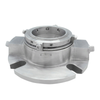
The Type 32 is an elastomer O-ring, multiple spring, hydraulically balanced, dry running seal supplied in metric
and inch sizes for outside mounting.
T
hese instructions apply to the seal as installed in a top entry mixer, agitator,
or reactor vessel, in accordance with the application information contained in
the John Crane technical document S-32-E, and any John Crane seal selection literature or process. Typical
operating limits are shown below.
The selection of materials used in the construction of a seal should be made with regard to their temperature
and chemical resistance/compatibility with the product.
Temperature Limits:
_
45°C to +150°C /
_
50°F to +300°F
(Depending on the materials used.)
Pressure Limits: Full vacuum to 15 bar g / 225 psig (refer to PV graph)
Speed Limits: Up to 2 m/s / 400 fpm
Type 32 Seal Installation Dimensions
10
9
2
3
8
6
11
1
4
5
7
L39
52.4±0.25
WORKING
HEIGHT
ÿD3
ÿD±0.05
SHAFT DIA.
Typical Type 32 Seal Arrangement
Part Name
1 Face/Primary Ring
2 O-Ring
3 Retainer
4 Thrust Ring
5 Spring
6 T-Bar
7 Cap Head Screw
8 Set Screw
9 O-Ring
10 Seat/Mating Ring
and Gaskets*
11 Gland Plate
*Refer to seat/mating
ring instruction manual
Question and Answer IconNeed help?

Do you have a question about the John Crane 32 and is the answer not in the manual?

Overview

The John Crane Type 32 is an elastomer O-ring, multiple spring, hydraulically balanced, dry running mechanical seal designed for sealing rotating shafts in various industrial applications. It is supplied in both metric and inch sizes and is specifically intended for outside mounting.

Function Description:

The primary function of the Type 32 seal is to prevent leakage of process fluids or gases from rotating equipment, such as top entry mixers, agitators, or reactor vessels. It achieves this by creating a dynamic seal between a rotating shaft and a stationary housing. The design incorporates multiple springs to provide uniform face loading and an O-ring for static sealing. The hydraulic balance feature helps to reduce the forces acting on the seal faces, thereby extending its lifespan and improving performance. The dry running capability means it can operate without external lubrication to the seal faces, simplifying system design and reducing potential contamination. An optional debris well is available to protect the process liquid or gas from contamination by face wear particles, forming a cavity to isolate and contain face debris, with tapped connections for flushing during cleaning cycles.

Important Technical Specifications:

  • Seal Type: Elastomer O-ring, multiple spring, hydraulically balanced, dry running mechanical seal.
  • Mounting: Outside mounting.
  • Temperature Limits: -45°C to +150°C (-50°F to +300°F), depending on the materials used in construction.
  • Pressure Limits: Full vacuum to 15 bar g (225 psig). The Pressure/Velocity (PV) limits graph indicates maximum operating pressures based on seal size and RPM, with specific conditions for carbon graphite face/primary ring against silicon carbide or tungsten carbide seat/mating ring, and sealed fluid at 80°C (175°F). Maximum static/test pressures are 1.5 times the relevant maximum operating pressure.
  • Speed Limits: Up to 2 m/s (400 fpm).
  • Materials: The selection of materials for the seal's construction is crucial and should be made with regard to their temperature and chemical resistance/compatibility with the product.
  • Shaft Run-Out: Maximum 0.08 mm (0.003 in.) F.I.M.
  • Shaft/Sleeve End Play/Axial Float: Maximum ±1.60 mm (±0.063 in.).
  • Seal Housing Face Squareness: Maximum 0.08 mm (0.003 in.) F.I.M.
  • Seal Housing Bore Concentricity: Maximum 0.08 mm (0.003 in.) F.I.M.
  • Shaft/Sleeve Finish: 0.2 to 1.2 µm Ra.
  • Shaft/Sleeve Hardness: 50 to 60 Rc.
  • Shaft/Sleeve Out-of-Roundness/Taper: 0.025 mm (0.001 in.) F.I.M.
  • Gland Plate Thickness: The thickness of the gland plate must be sufficient to retain the service pressure without distortion.
  • Working Height: 52.4 ± 0.25 mm.

Usage Features:

  • Installation: The installation process involves removing protective packaging, checking for damage, and cleaning the seal. The seat/mating ring and gland plate are fitted as per the seat instruction manual, with an optional debris well if required. Lubricants like soft hand soap and water, glycerine, or silicone grease are recommended for elastomer O-rings, avoiding hydrocarbon-based liquids on ethylene propylene elastomers. The shaft should be clean and sparingly lubricated. Special care must be taken to avoid damaging lapped surfaces and flexible sealing rings during installation, particularly when passing the seal over shaft shoulders. The seal unit is slid onto the shaft until the seal face rests on the seat/mating ring, then compressed to the correct working height, aligning the back of the retainer with the seal setting mark. Set screws are tightened evenly and progressively to the recommended torque values.
  • Setting the Seal: Accurate setting of the seal to its correct working height is critical to prevent leakage (if undercompressed) or high wear (if overcompressed). The true seal position can be determined either by measuring L39 from the seal housing/vessel face before seat/mating ring installation, or by measuring from the face of the seat/mating ring after its installation.
  • Debris Well Option: This feature allows for the isolation and containment of face debris, with tapped connections for flushing, which is beneficial in applications where process liquid or gas must be protected from contamination.
  • Safety: The manual emphasizes safety instructions, including the requirement for qualified personnel to perform installation and removal, the exclusive use of the seal for sealing rotating shafts, and adherence to recommended performance limits. It also highlights precautions for handling hazardous or toxic fluids and warns against burning or incinerating PTFE and fluorocarbon components due to highly toxic fumes.

Maintenance Features:

  • Periodic Inspection: Regular inspection of the seal during operation is recommended. Leakage level serves as an indicator of seal condition.
  • Replacement: Since no maintenance is possible while the seal is installed, it should be replaced when leakage becomes unacceptable. It is advisable to keep a spare seal unit and seat/mating ring in stock for immediate replacement.
  • Decommissioning: Before decommissioning, the vessel must be electrically isolated, and if hazardous fluids were used, the equipment must be correctly decontaminated and made safe. The vessel should be isolated by appropriate valves, and the product drained with pressure fully released.
  • Removal: The equipment needs to be dismantled sufficiently to expose the seal. The seal is then removed, followed by the gland plate and seat/mating ring in reverse order of installation.
  • Servicing: Used seals should always be serviced after removal from duty. It is recommended to return them to a John Crane service location for rebuilding to as-new specification by qualified personnel. The equipment user is responsible for ensuring appropriate safe-handling instructions are externally attached to any package sent to a third party.

John Crane 32 Specifications

General IconGeneral
BrandJohn Crane
Model32
CategoryIndustrial Equipment
LanguageEnglish

Related product manuals