TYPE 32
In
st
a
lla
t
i
on
,
Oper
a
t
i
on
&
Ma
i
n
t
en
a
n
c
e In
st
r
u
c
t
i
on
s
PAG
E
2
Take particular care to
a
The manufacturer
c
Seal Seal
Size Size D D3 L39
(mm) Code
25 0250 25 63.5 †
28 0280 28 66.7 †
30 0300 30 69.9 †
32 0320 32 69.9 †
33 0330 33 73.0 †
35 0350 35 73.0 †
38 0380 38 76.2 †
40 0400 40 79.4 72.9
43 0430 43 82.6 73.0
45 0450 45 85.7 73.0
50 0500 50 88.9 77.8
53 0530 53 92.1 77.8
55 0550 55 95.3 78.4
58 0580 58 98.4 77.8
60 0600 60 98.4 77.8
63 0630 63 101.6 77.8
65 0650 65 104.8 78.4
68 0680 68 108.0 77.8
70 0700 70 108.0 77.8
75 0750 75 114.3 77.8
Seal Seal
Size Size D D3 L39
(mm) Code
80 0800 80 120.7 77.8
85 0850 85 123.8 77.8
90 0900 90 130.2 78.4
95 0950 95 133.4 77.8
100 1000 100 139.7 80.4
105 1050 105 142.9 77.8
110 1100 110 149.2 77.8
115 1150 115 155.6 79.4
120 1200 120 158.8 79.4
125 1250 125 165.1 79.4
130 1300 130 168.3 79.4
135 1350 135 174.6 79.4
140 1400 140 181.0 79.4
145 1450 145 184.2 79.4
150 1500 150 190.5 79.4
155 1550 155 193.7 79.4
160 1600 160 200.0 79.4
165 1650 165 203.2 79.4
170 1700 170 209.6 79.4
175 1750 175 215.9 †
Seal Seal
Size Size D D3 L39
(inches) Code
1.000 0254 25.40 63.5 †
1.125 0285 28.58 66.7 †
1.250 0317 31.75 69.9 †
1.375 0349 34.93 73.0 †
1.500 0381 38.10 76.2 †
1.625 0412 41.28 79.4 72.9
1.750 0444 44.45 82.6 73.0
1.875 0476 47.63 85.7 73.0
2.000 0508 50.80 88.9 77.8
2.125 0539 53.98 92.1 77.8
2.250 0571 57.15 95.3 78.4
2.375 0603 60.33 98.4 77.8
2.500 0635 63.50 101.6 77.8
2.625 0666 66.68 104.8 78.4
2.750 0698 69.85 108.0 77.8
2.875 0730 73.03 111.1 77.8
3.000 0762 76.20 114.3 77.8
3.125 0793 79.38 117.5 77.8
3.250 0825 82.55 120.7 77.8
3.375 0857 85.73 123.8 77.8
Seal Seal
Size Size D D3 L39
(inches) Code
3.500 0889 88.90 127.0 77.8
3.625 0920 92.08 130.2 78.4
3.750 0952 95.25 133.4 77.8
3.875 0984 98.43 136.5 77.8
4.000 1016 101.60 139.7 80.4
4.125 1047 104.78 142.9 77.8
4.250 1079 107.95 146.1 77.8
4.375 1111 111.13 149.2 77.8
4.500 1143 114.30 152.4 79.4
4.625 1174 117.48 155.6 79.4
4.750 1206 120.65 158.8 79.4
4.875 1238 123.83 161.9 79.4
5.000 1270 127.00 165.1 79.4
5.125 1301 130.18 168.3 79.4
5.250 1333 133.35 171.5 79.4
5.375 1365 136.53 174.6 79.4
5.500 1397 139.70 177.8 79.4
5.625 1428 142.88 181.0 79.4
5.750 1460 146.05 184.2 79.4
5.875 1492 149.23 187.3 79.4
C S S
C Sales/Service Engineer
P
M
etric Range Dimensional Data (mm) (Cont.)
M
etric Range Dimensional Data (mm)
I
nch Range Dimensional Data (mm)
†
For these dimensions contact your John Crane.
† For these dimensions contact your John Crane Representative
Seal Seal
Size Size D D3 L39
(inches) Code
1.000 0254 25.40 63.5 †
1.125 0285 28.58 66.7 †
1.250 0317 31.75 69.9 †
1.375 0349 34.93 73.0 †
1.500 0381 38.10 76.2 †
1.625 0412 41.28 79.4 72.9
1.750 0444 44.45 82.6 73.0
1.875 0476 47.63 85.7 73.0
2.000 0508 50.80 88.9 77.8
2.125 0539 53.98 92.1 77.8
2.250 0571 57.15 95.3 78.4
2.375 0603 60.33 98.4 77.8
2.500 0635 63.50 101.6 77.8
2.625 0666 66.68 104.8 78.4
2.750 0698 69.85 108.0 77.8
2.875 0730 73.03 111.1 77.8
3.000 0762 76.20 114.3 77.8
3.125 0793 79.38 117.5 77.8
3.250 0825 82.55 120.7 77.8
3.375 0857 85.73 123.8 77.8
Seal Seal
Size Size D D3 L39
(inches) Code
3.500 0889 88.90 127.0 77.8
3.625 0920 92.08 130.2 78.4
3.750 0952 95.25 133.4 77.8
3.875 0984 98.43 136.5 77.8
4.000 1016 101.60 139.7 80.4
4.125 1047 104.78 142.9 77.8
4.250 1079 107.95 146.1 77.8
4.375 1111 111.13 149.2 77.8
4.500 1143 114.30 152.4 79.4
4.625 1174 117.48 155.6 79.4
4.750 1206 120.65 158.8 79.4
4.875 1238 123.83 161.9 79.4
5.000 1270 127.00 165.1 79.4
5.125 1301 130.18 168.3 79.4
5.250 1333 133.35 171.5 79.4
5.375 1365 136.53 174.6 79.4
5.500 1397 139.70 177.8 79.4
5.625 1428 142.88 181.0 79.4
5.750 1460 146.05 184.2 79.4
5.875 1492 149.23 187.3 79.4
Seal Seal
Size Size D D3 L39
(inches) Code
6.000 1524 152.40 190.5 79.4
6.125 1555 155.58 193.7 79.4
6.250 1587 158.75 196.9 79.4
6.375 1619 161.93 200.0 79.4
6.500 1651 165.10 203.2 79.4
6.625 1682 168.28 206.4 79.4
6.750 1714 171.45 209.6 79.4
6.875 1746 174.63 212.7 †
7.000 1778 177.80 215.9 †
† F h di i J h C S l /S i E i
Inch Range Dimensional Data (in)
I
nch Range Dimensional Data (i) (Cont.)
Inch Range Dimensional Data (in) (Cont.)
† For these dimensions contact your John Crane Representative
Lead-On Chamfer
For ease of installation, the lead-on edge of the shaft or sleeve should be
chamfered as shown.
P 2.5 mm
Q 10°
R 1mm RADIUS
Checking the Equipment
Successful operation and life of this seal is dependent on acceptable equipment
dimensions, alignments, and finishes. Before installation of the seal, the following
checks should be made with respect to the seal housing and the shaft, especially
(where marked
†)
at the seal position. The usual equipment to measure these fea-
tures would include a micrometer and dial indicator.
Shaft/Sleeve Outside Diameter
†
Refer to Dimension Tables
Shaft/Sleeve Finish
†
0.2 to 1.2 µm Ra
Shaft/Sleeve Ovality/Out-of-Roundness
†
< 0.05 mm / 0.002 in.
Shaft End Play/Axial Float ± 1.60 mm / 0.063 in.
Shaft/Sleeve Run-Out
†
< 3.81 mm / 0.150 in. F.I.M.
Shaft/Sleeve Lead-On Refer to Lead-On Chamfer
Seal Housing End Face Squareness < 0.80 mm / 0.031 in. F.I.M.
to Shaft/Sleeve
NOTE: If the measured dimensions exceed the values given, correct the equipment
to meet the specifications before installing the seal. If the seal is installed on
a sleeve, the sleeve must be liquid- and pressure-tight through its bore. The
thickness of the gland plate must be sufficient to retain the service pressure
without distortion.
Operating Conditions
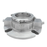
The Type 32 is an elastomer O-ring, multiple spring, hydraulically balanced, dry running
seal supplied in metric and inch sizes for outside mounting.
These instructions apply to the seal as installed in a top entry mixer, agitator,
or reactor vessel, in accordance with the application information contained in
the John Crane technical document S-32-E, and any John Crane seal selection litera-
ture or process. Typical operating limits are shown below.
The selection of materials used in the construction of a seal should be made with
regard to their temperature and chemical resistance/compatibility with the product.
Temperature Limits:
_
45°C to +150°C /
_
50°F to +300°F
(Depending on the materials used.)
Pressure Limits: Full vacuum to 15 bar g / 225 psig (refer to PV graph)
Speed Limits: Up to 2 m/s / 400 fpm
 Loading...