Installation, Operation & Maintenance Instructions
3
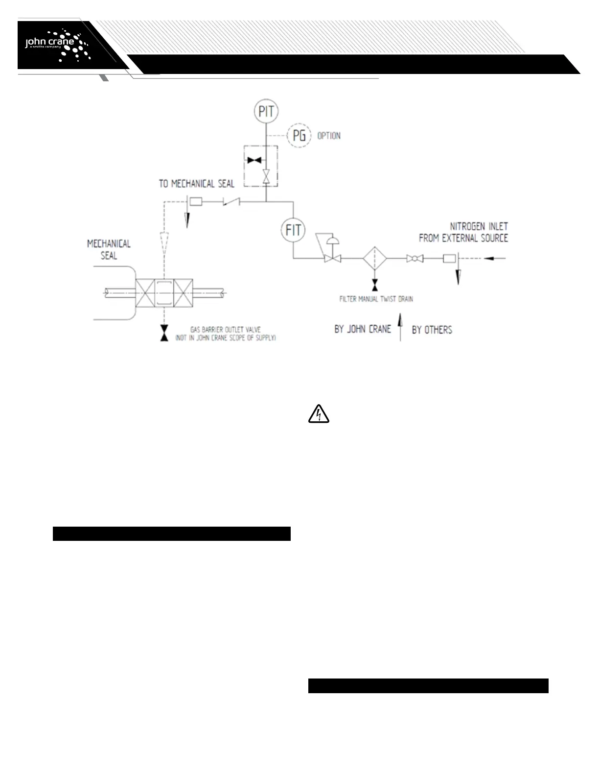
API PLAN 74
SEAL SYSTEMS
4.2 Instrumentation and fittings
The system is usually supplied with the following:
•
Barrier gas supply inlet (flanged or threaded)
•
Panel outlet to seal (flanged or threaded)
•
Pressure indicating transmitter (PIT)
•
Flow indicating transmitter (FIT)
And, upon request with the following options:
•
Pressure gauge (PG)
•
Pressure switch (PS) instead of a PIT
•
Flow indicator (FI) instead of FIT
•
Flow switch (FS) with the flow indicator
5. Installation and Assembly
5.1 Before installation
Prior to installation ensure that internally all connecting pipe work
has been thoroughly cleaned. Remove protection caps from pipes and
connections. Check all fittings/connections for damage replacing if
necessary.
5.2 Control panel mounting
Refer to the appropriate arrangement drawing for mounting details.
It is recommended that piping between the Plan 74 control panel and
the mechanical seal should be kept below 2 metres (72 inches) in length
wherever possible. If this length is exceeded, consideration should be
given to increased frictional losses and, if necessary, allowances must be
made when setting the seal pressure.
It is advisable to install a vent connection in the interconnecting
pipe work close to the seal chamber.
With the gas supply isolated, connect the barrier gas supply piping to
the inlet connection on the Plan 74 control panel and connect the panel
outlet connection to the mechanical seal gas barrier in (GBI) connection.
Do not open gas supply at this time.
5.3 Electrical connections
Only authorized and qualified personnel are permitted to
carry out work on electrical systems. International and
local safety regulations must be followed in all cases.
Before connecting cables, check the electrical data on the name plate
matches the available power supply and complies with the area hazard
classification.
Refer to the diagrams in the terminal housing and the supplier's
instruction manual for wiring instructions. Connect the electrical
component using flexible conduit or armoured cable to assist removal of
the component for maintenance purposes.
If passive switching elements are installed in potentially explosive areas
you should add suitable protective devices, following the pertinent rules.
5.4 Leak check
During transit, tube fittings may work loose, check all fittings/
connections for tightness. First checking that the barrier gas supply
pressure is within the limits of the Plan 74 control panel, slowly open
the barrier gas supply line isolation valve allowing the control panel to
pressurize.
Using a suitable leak testing liquid check all joints and if necessary,
rectify any leaks found.
6. Commissioning and Decommissioning
6.1 Commissioning
Before starting the machine (pump or mixer) carry out the following
operations:
 Loading...