WARNING: THIS APPLIANCE MUST BE EARTHED
This appliance is for use with liquid petroleum gas G31, and is approved for use in GB, IE, FR, NL BE & NO,
IMPORTANT: STATUTE LAW DEFINES THAT ALL GAS APPLIANCES MUST BE INSTALLED, COMMISSIONED
AND MAINTAINED BY COMPETENT PERSONS, (ie CORGI REGISTERED INSTALLERS) IN ACCORDANCE
WITH THE GAS SAFETY (INSTALLATION AND USE) REGULATIONS (CURRENT EDITION). FAILURE TO
COMPLY WITH THESE REGULATIONS MAY LEAD TO PROSECUTION.
1. BRIEF DESCRIPTION
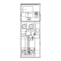
1 Air Filter
2 Air circulating fan
3 Fuse
4 Time control
5 Data plate
6 Fan Delay Control
7 Multifunctional control
8 Pilot burner
9 Main burner assembly
10 Gas connection
11 Limit Switch
12 Control panel
13 Piezo unit
14 Summer air circulation switch
15 Spillage monitor device (TTB) (at rear)
16 Draught Diverter
Fig. 1
1.1 JB25P is an open-flued, fan assisted downflow, ducted warm air heater. A Spillage Monitoring Device is fitted which
senses the temperature around the draught diverter, and shuts down the appliance when this temperature rises due to the
presence of flue gases.
1.2 The Air heater output is 7.6kW (27.5MJ/h, 26,000Btu/h). “Summer air circulation” of unheated air is available by manual
selection (see User’s Instructions).
1.3 For Caravan installations, Slot Fit Kit ATL30 is available for this appliance. For Permanent Dwellings, Free-Standing Kit
TC30 and Slot Fit Kits TS30 and TSA30 are available for this appliance.
THIS APPLIANCE CONFORMS TO BS EN 55014
JB25P MK 5 WARM AIR HEATER
INSTALLATION, COMMISSIONING & SERVICING INSTRUCTIONS
G.C. No 42 416 13
Publication No. ZZ 1031/4
August 2004
These instructions are to be left with the User or adjacent to the Gas Appliance
1
Johnson and Starley prides itself on its ability to supply spare parts quickly and efficiently. If you have a problem in
obtaining a spare part, please contact Johnson and Starley Spares Department at the address below.
JOHNSON & STARLEY LTD.
Telephone: (01604) 762881 Rhosili Road,
Brackmills,
Telefax: (01604) 767408 Northampton NN4 7LZ
1
9
8
5
14
2
16
15
12
3
4
11
6
7
13
10
10. SHORT LIST OF SPARES
ITEM G.C. MAKER’S DESCRIPTION QTY
No No No
1 381 732 1000-0500130 Fan assembly 1
2 244 925 B300-0182000 Filter tray assembly 1
3 232 962 CL2S Time control CL2 1
4 244 926 1000-0000070 Time control cover 1
5 384 739 BOS 00105 Limit Switch 1
Honeywell L4069C
6 H26-712 1000-0709640 Multifunctional control 1
Honeywell V8600C 1129
7 232 903 BOS 02061 Sealing ring (for item 6) 2
8 173 096 1000-0704810 Pilot assembly 1
9 E01 088 1000-0703070 Pilot Injector SIT 0.977.149-(15) 1
10 386 820 1000-0703870 Thermocouple SIT 0.290.174 1
11 386 775 BOS 01970 Electrode 1
12 397 819 1000-0705400 Electrode lead 1
13 244 898 BOS 02406 Electrode Nut 1
14 E02 398 B302-0116000 Spillage switch (TTB) 1
15 B265-0800000 Burner and Control Assembly 1
16 E00 411 1000-0705070 Main Burner Arm Furigas 174.500.016 1
17 1000-0708140 Main Injector Bray Cat 23/380 1
18 E02 399 B264-0300005 Heat Exchanger exchange kit 1
19 386 571 1000-0700570 Piezo Unit 1
20 E02 391 B302-0707000 Igniter Bracket 1
21 244 957 1000-2500010 Rope Ring Seal (heat exchanger access cap) 1
22 244 927 1000-0500275 Control Panel 1
23 E02 392 1000-0517730 Wiring Harness 1
24 385 159 BOS 00104 Fan Control Honeywell L4068C-1125 1
25 245 504 1000-0513820 Fuse 3.15A, (T) 1