10 A419 Series Electronic Temperature Controls with Display and NEMA 1 or NEMA 4X Watertight Enclosures
Product/Technical Bulletin
2. Check for proper sensor operation.
Disconnect all power sources to control.
a. Take a temperature reading at the sensor
location, using an accurate thermometer.
b. Disconnect the sensor from the control.
c. Use a reliable ohmmeter, to measure the
resistance across the two sensor leads while
the sensor is at the temperature taken in
Step b.
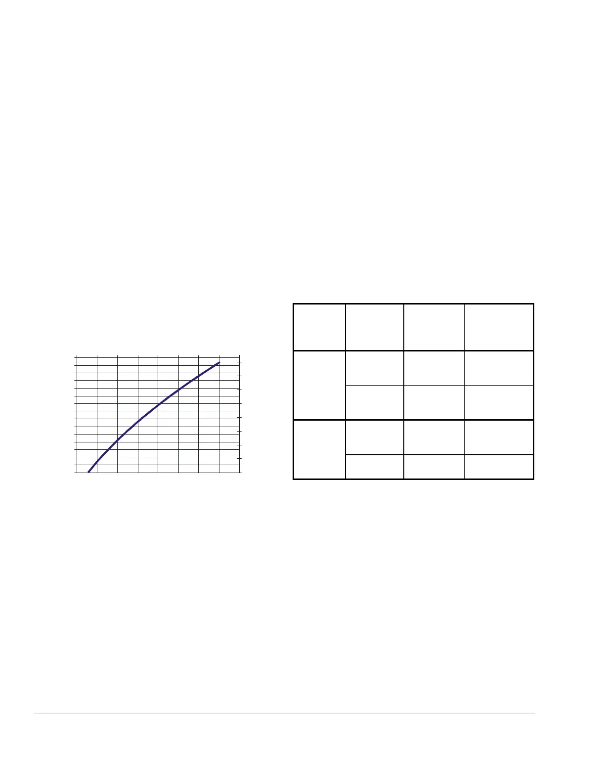
d. Refer to Figure 15 to verify that the measured
temperature and resistance conform to
established temperature and resistance
values.
e. If the measured values conform to the values
in Figure 15, proceed to Step 3.
f. If the sensor’s measured resistance value is
substantially different from the expected value
for that temperature, check the sensor wiring.
If sensor wiring is okay, replace the sensor.
-40
-20
0
20
40
60
80
100
120
140
160
180
200
220
240
260
500 700 900 1100 1300 1500 1700 1900 2100
Resistance in Ohms
Temperature
°F
-40
-20
0
20
40
60
80
100
120
Temperature
°C
Figure 15: Nominal Temperature vs.
Sensor Resistance
3. Check the A419 for proper operation.
a. Perform Troubleshooting Steps 1 and 2 before
performing this step.
b. Disconnect the load from the output relay
terminals.
c. Ensure that the Touchpad Lock jumper is
installed, so that the touchpad is unlocked.
d. Reconnect the sensor leads and supply power
to the control.
e. Replace the cover.
f. Check the control settings for proper values.
g. Press and hold the MENU button until Setpoint
appears (occurs in about 2 seconds).
h. Use the Up and Down buttons to change the
Setpoint temperature above and below the
current sensor temperature until the output
relay energizes and de-energizes as shown in
Table 4.
If the anti-short cycle delay has a time greater
than 0 minutes, the relay will not energize until
the timed delay has elapsed.
i. If the output relay does not perform as
indicated in Table 4, replace the A419 control.
j. If proper operation of the A419 control is
verified, reconnect the load and consult the
equipment manufacturer’s instructions for
troubleshooting the controlled equipment.
Table 4: A419 Output Relay Operation
Setpoint
Mode
Operating
Mode
Output
Relay
Energized
at…
Output Relay
De-energized
at…
Cooling
Setpoint
plus
differential
Setpoint
Cutout
Heating
Setpoint
minus
differential
Setpoint
Cooling Setpoint
Setpoint
minus
differential
Cut-in
Heating Setpoint
Setpoint plus
differential
Note: When the relay is energized, the N.O. contacts
are closed and the LED is illuminated.