Installation Sheets Manual 121
Temperature Controls Section
Technical Bulletin A70, A72
Issue Date 0591
© 1991 Johnson Controls, Inc. 1
Code No. LIT-121121
Part No. 997-202, Rev. E
A70, A72 Series Temperature Controls A70 Single-Pole and
Four-Wire Two-Circuit A72 Two-Pole Construction
Application
The A70 single-pole and A72
two-pole controls incorporate a
load-carrying, contact structure
which provides direct control of
AC motors within the control
rating. (See cover label for
electrical rating.)
All Series A70, A72 controls are
designed for use only as
operating controls. Where an
operating control failure would
result in personal injury and/or
loss of property, it is the
responsibility of the installer to
add devices (safety, limit
controls) or systems (alarm,
supervisory systems) that
protect against, or warn of,
control failure.
Operation
Controls are available with either
CLOSE high -- OPEN low or
OPEN high -- CLOSE low
contact action for heating or
refrigeration applications. The
snap-acting contacts are
operated by a temperature
sensing element. On the
A70 controls with auxiliary
contact, the auxiliary contact
closes to actuate a signal or
other auxiliary circuit at the
same time the main contact
opens. (See Fig. 6.)
Installation
Mounting
The A70 control in the NEMA 1
enclosure must be located in
areas protected from the direct
effects of weather. If the control
is directly exposed to the
weather or other wet
environments, it must be
equipped with an outdoor
enclosure. Mount the control on
a flat surface or panel board by
two screws or bolts through the
holes in the back of the case.
Controls are supplied without
brackets unless specified. The
standard bracket is Part Number
271-350. The desired mounting
position is with the element
bellows pointing down.
General Instructions
1. Avoid sharp bends or kinks
in the capillary tubing.
2. Style 1 (for clamp contact or
liquid immersion) -- be sure
the bulb is securely
clamped to the evaporator
coil, or is completely
immersed in the liquid.
3. Style 18 for air temperature
control -- locate the bulb
where there is free air
circulation. Make sure the
bulb does not contact a wall
surface.
4. Make sure the equipment's
electrical load is not in
excess of the control's
electrical rating.
5. Coil and secure the excess
capillary length to avoid
vibration. Allow some slack
in the capillary to avoid
“violin string” vibration which
can cause the tubing to
break. Do not allow the
tubing to rub against metal
surfaces where friction can
damage the capillary.
6. Do not use the control on
applications where
temperature exceeds the
maximum allowable
temperature. See the
Maximum Bulb Temperature
table.
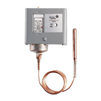
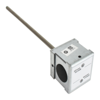
Fig. 1 -- A70 Temperature
Control with a style 1 sensing
element.