EasyManua.ls Logo

Johnson Controls A419 Series User Manual

Johnson Controls A419 Series
12 pages
To Next Page IconTo Next Page
Page #1 background imageLoading...
Page #1 background image
Product/Technical Bulletin A419
Issue Date February 10, 2003
© 2003 Johnson Controls, Inc.
1
Code No. LIT-125188 www.johnsoncontrols.com
®
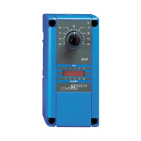
A419 Series Electronic Temperature Controls with Display
and NEMA 1 or NEMA 4X Watertight Enclosures
The A419 series controls are single-stage, electronic
temperature controls with a Single-Pole, Double-Throw
(SPDT) output relay. They feature a lockable
front-panel touchpad for setup and adjustment, and a
Liquid Crystal Display (LCD) for viewing the
temperature and status of other functions. A
Light-Emitting Diode (LED) indicates the controls’
output relay On/Off status. The A419 controls are
available in 24 VAC or 120/240 VAC powered models.
The A419 controls have heating and cooling modes,
adjustable setpoint and differential, an adjustable
anti-short cycle delay, and a temperature offset
function. The setpoint range is -30 to 212°F
(-34 to 100°C). The controls feature remote sensing
capability and interchangeable sensors. The
A419 controls are available in either NEMA 1,
high-impact plastic enclosure suitable for surface or
DIN rail mounting or NEMA 4X watertight,
corrosion-resistant surface-mount enclosures.
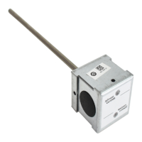
Figure 1: A419 Temperature Control with NEMA 1
Enclosure and A99 Temperature Sensor
Features and Benefits
Easy-to-Read Front-Panel
Liquid Crystal Display
Displays the sensed temperature and control-function
status clearly; custom icons on the display indicate the
control and system status at a glance
Wide Temperature Differential Adjustment
Range (1 to 30F° or C°)
Allows the user to set a precise (1F° or C°) temperature
differential from 1 to 30F° or C°; providing a much
tighter differential than electromechanical controls
Adjustable Anti-Short Cycle Delay
(0 to 12 Minutes in 1-Minute Increments)
Ensures that the output relay remains off for a user-set
time delay, which helps avoid hard starts, nuisance
overload outages, and unnecessary equipment wear
Switch-Activated Temperature Offset
Function
Allows the user to shift the cut-in and cutout setpoints
by an adjustable offset based on the status of a
user-installed, external switch, such as a time clock
High-Impact, Thermoplastic NEMA 1 or
NEMA 4X Watertight, Corrosion-Resistant
Enclosures
Increase application options, allowing surface and
snap-fit DIN rail mount, or Watertight surface mount
Lockable Front Panel Touchpad Allows easy set up and adjustment of the A419 control
setpoint, differential, and other functions; a concealed
jumper locks the touchpad, and deters unauthorized
adjustment of the control settings
Low- and Line-Voltage Models
Provide options for most refrigeration and HVAC
control-voltage applications

Other manuals for Johnson Controls A419 Series

Questions and Answers:

Johnson Controls A419 Series Specifications

General IconGeneral
Control TypeOn/Off
Supply Voltage120/208/240 VAC
Switch TypeSPDT
Output TypeRelay
Accuracy±1°F (±0.5°C)
DisplayLED
Enclosure RatingNEMA 1
DifferentialAdjustable
Sensor TypeThermistor
MountingSurface
Output Relay Rating16A (Resistive), 1/2 HP (Inductive)

Summary

A419 Series Electronic Temperature Controls

Product Description

Single-stage electronic temperature controls with SPDT output relay, LCD display, and NEMA 1 or NEMA 4X enclosures.

Easy-to-Read Front-Panel Liquid Crystal Display

Displays sensed temp, status, and custom icons for control and system status.

Wide Temperature Differential Adjustment Range

Allows precise temp diff setting (1-30F°/C°) for tighter control than electromechanical units.

Adjustable Anti-Short Cycle Delay

Prevents rapid cycling by maintaining relay off-time, protecting equipment.

Switch-Activated Temperature Offset Function

Shifts cut-in/cutout setpoints based on an external switch, like a time clock.

High-Impact Enclosures (NEMA 1 & NEMA 4X)

Offers NEMA 1 for surface/DIN rail and NEMA 4X for watertight, corrosion-resistant applications.

Lockable Front Panel Touchpad

Enables easy setup/adjustment, with a jumper to lock touchpad and deter unauthorized changes.

Low- and Line-Voltage Models

Provides options for most refrigeration and HVAC control-voltage applications.

Application and Compliance

Intended Use and Safety

Controls are for normal operation; safety devices must be integrated to protect against failure or malfunction.

Typical Applications

Used for refrigeration, HVAC equipment like freezers, coolers, boilers, and fans.

Regulatory Compliance

Details compliance with FCC Part 15 rules and Canadian Radio Interference Regulations.

Control Operation and Interface

Operation Overview

Explains the front panel components (LCD, LED) and how control functions are described.

Front Panel Interface Details

Details the Liquid Crystal Display (LCD), Output Relay Status Indicator LED, and touchpad buttons for operation.

Control Function Definitions

Defines Cut-in (relay closes) and Cutout (relay opens) temperatures relative to the SPDT output relay.

Front-Panel Adjustable Functions

Covers Setpoint (SP), Differential (dIF), and Anti-Short Cycle Delay (ASd) adjustment via the front panel.

Advanced Configuration Options

Sensor Failure Operation (SF)

Defines operation during sensor or sensor-wiring failures (continuous run or shutdown).

Temperature Unit and Offset Settings

Covers changing display units (F°/C°) and applying temperature offset via binary input.

Jumper Configuration Options

Explains how jumpers set Touchpad Lock, Heating/Cooling mode, and Setpoint mode (cut-in vs. cutout).

Operating Modes Explained

Details the four operating modes: Cooling/Cut-in, Cooling/Cutout, Heating/Cut-in, and Heating/Cutout.

Physical Installation and Wiring

Enclosure Types and Mounting

Describes NEMA 1 and NEMA 4X enclosures and provides guidance on mounting.

Wiring Guidelines

Emphasizes electrical safety, wire types, and provides typical wiring diagrams for different voltage models.

Sensor and Offset Wiring Details

Guidelines for sensor lead length, resistance, interference, and wiring for the Temperature Offset function.

Adjustments and Setup Procedures

Jumper Positioning for Settings

Details jumper placement on P4 and P5 to configure mode, setpoint type, and touchpad lock.

Changing Temperature Units

Procedure to convert temperature display between Fahrenheit and Celsius units.

Setting the Setpoint

Step-by-step guide for adjusting the temperature setpoint using the control's buttons.

Setting Other Functions

Instructions for adjusting Differential (dIF), Anti-short Cycle Delay (ASd), Temperature Offset (OFS), and Sensor Failure (SF).

Troubleshooting and Maintenance

Checkout Procedure

Steps to verify installation, wiring, and control operation for three complete cycles before finalizing.

Troubleshooting Common Issues

Covers checking voltage, sensor operation (resistance vs. temp), and output relay function based on settings.

Fault Code Identification

Lists fault codes (SF, EE) displayed on the LCD and provides corresponding system status and solutions.

Repairs and Ordering Information

Advises against self-repair; provides guidance on contacting distributors and ordering information.

Technical Specifications

Product Specifications Summary

Details specifications including range, voltage, power, electrical ratings, and environmental conditions.

Related product manuals