Differential Pressure Transducer DP140 Series
Installation Guide
Introduction
The Johnson Controls
®
DP140 Series sense differential
or gauge (static) pressure and convert this pressure
difference to a proportional high-level analog output for
both unidirectional and bidirectional pressure ranges.
Every sensor in the DP140 Series is tested and calibrated
before shipment. Three standard excitation and output
versions are available. See Table 1.
Table 1: DP140 Series versions
Excitation Output Output codes
24 VDC or VAC 0 VDC to 5 VDC 1
24 VDC 4 mA to 20 mA 2
24 VDC or VAC 0 VDC to 10 VDC 3
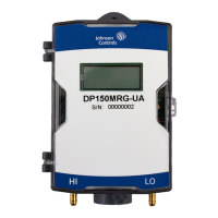
Figure 1: DP140 Series Transducer
Compatibility
Use the Johnson Controls DP140 transducers with air or
nonconducting gases.
Note: Use with liquids or corrosive gases damages
the unit.
The operating temperature limits of the DP140 are as
follows:
• Operating temperature: 0°F to 150°F (-18°C to 65°C)
• Compensated temperature range: 0°F to 150°F (-18°C to
65°C)
Mounting
The DP140 transducer includes 3/16 in. O.D. barbed brass
pressure fittings, installed with 1/4 in. push-on tubing. For
the shortest response times, use 3/16 in. I.D. for tubing
lengths up to 100 feet long, 1/4 in. I.D. for tubing lengths
up to 300 feet, and 3/8 in. I.D. for tubing lengths up to 900
feet. The static positive pressure port, labelled High, is
located on the bottom of the unit. The reference pressure
port, labelled Low, is located on the bottom of the unit.
Use the reference pressure port for differential pressure
measurements.
Installation
About this task:
Wiring is through a 1/2 in. threaded conduit opening.
Both current and voltage output units are reverse wiring
protected.
Note: Figure 2 shows the voltage output and Figure 3
shows the current output, both for electrical code 1.
Important: For voltage outputs, do not connect
+Excitation to +Out/Sig as this results in
unrecoverable damage to the board.
To install the DP140 transducer, complete the
following steps:
1. To access the terminal strip, pull the latch away
from the base to disengage the cover.
2. Swing open the cover to access the terminal block.
3. Identify wire terminals on the circuit board and the
diagram on the inside cover.
4. For voltage output, connect the wires as shown in
Figure 2.
Figure 2: Voltage output
Callout Description
A Readout or Data Access Server (DAS)
B DP140 Transducer
C Power supply
EXC Connect to positive terminal of DC or
AC power supply
COM Connect as the reference for power
supply and output signal
OUT Connect to positive terminal of control
or pressure monitor
5. For current ouput, connect the wires as shown in
Figure 3.
*241148600012-*
Part No. 24-11486-00012 Rev. —
2021-05-13
(barcode for factory use only)
DP140