6. Close the cover.
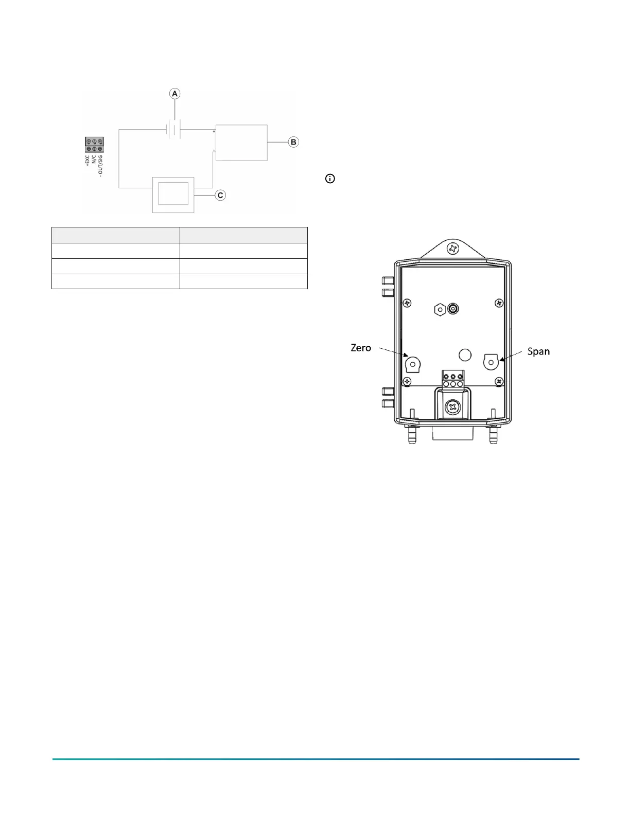
Figure 3: Current output
Callout Description
A 9 VDC to 30 VDC
B DP140 Transducer
C Current monitor device
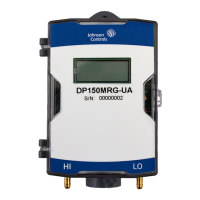
Calibration
The DP140 is factory-calibrated for installation on a
wall or other vertical surface, which requires no field
adjustment. If you mount the DP140 on a horizontal
surface, a slight zero shift may occur that depends on
the range of the sensor. Correct any zero or span shift
by software adjustment in the user’s control system. For
calibration, access both zero and span potentiometers
under the cover of the unit, on either side of the terminal
strip. See Figure 4.
Note: A trained individual must complete
calibrations with the correct equipment and
standards for the pressure range of the DP140.
Figure 4: Calibration of the DP140 transducer
Differential Pressure Transducer DP140 Series Installation Guide2