2 F61 Series Standard Flow Switches Installation Instructions
Dimensions
4
(102)
2
(51)
Diameter Hole for 1/2 in. Trade Size Conduit
1-1/16
(27)
Diameter Knockout Ring for 3/4 in. Trade Size Conduit
7/8
(22)
2-3/4
(71)
1-3/8
(35)
2-11/16
(68)
1-3/4
(44)
B
A
4-3/4
(121)
1-1/8
(29)
Grounding
Screw
Hole
1-1/4
(33)
Use these
wrench flats
to tighten
the flow switch
at installation.
Paddle
Screw
1 in.
11-1/2 NP T
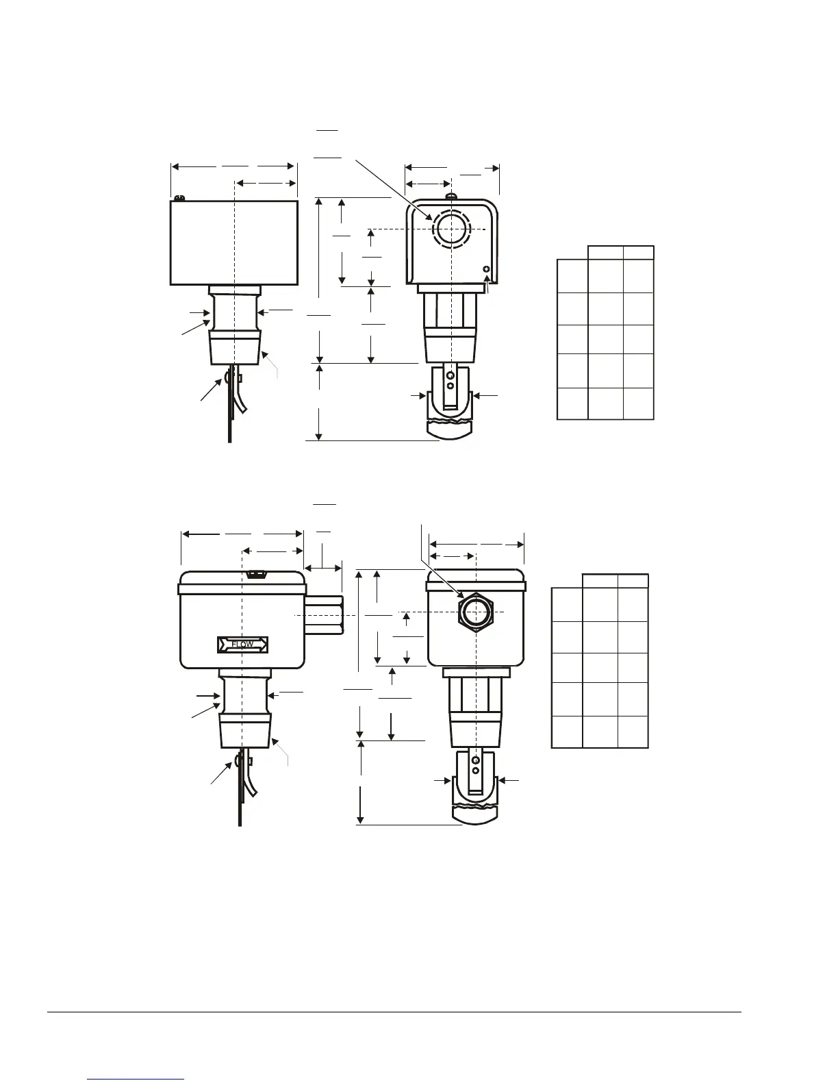
Dimension by
Liquid Line Size
BA
1-7/16
(37)
1
(25)
2-1/2
(64)
1-1/8
(29)
1-1/8
(29)
1-1/8
(29)
1-1/8
(29)
1
(25)
2
(51)
3
(76)
3-1/2
(89)
4
(101)
6-5/8
(168)
6-5/8
(168)
5
(152)
Figure 3: NEMA 1 Enclosure (F61KB Types) Dimensions, in./mm
1 in. 11-1/2 NPT
Use these
wrench flats
to tighten
the flow switch
at installation.
Paddle
Screw
2-3/4
(71)
1-3/8
(35)
2-7/8
(73)
1-9/16
(40)
4-3/4
(121)
1-1/16
(27)
B
A
1-1/4
(33)
3-11/16
(94)
1-13/16
(47)
1-1/8
(29)
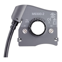
On MB and MG Types
5/8
(15)
On LB Types
1/2-14 NPSM Thread
Dimension by
Liquid Line Size
BA
1-7/16
(37)
1
(25)
2-1/2
(64)
1-1/8
(29)
1-1/8
(29)
1-1/8
(29)
1-1/8
(29)
1
(25)
2
(51)
3
(76)
3-1/2
(89)
4
(101)
6-5/8
(168)
6-5/8
(168)
5
(152)
Figure 4: NEMA 3 or NEMA 3R Enclosure (F61LB, F61MB, F61MG Types) Dimensions, in./mm