4 F61 Series Standard Flow Switches Installation Instructions
IMPORTANT: Install all wiring in accordance with
the National Electrical Code and local regulations.
Make all wiring connections using copper conductors
only. Do not exceed the control’s electrical rating.
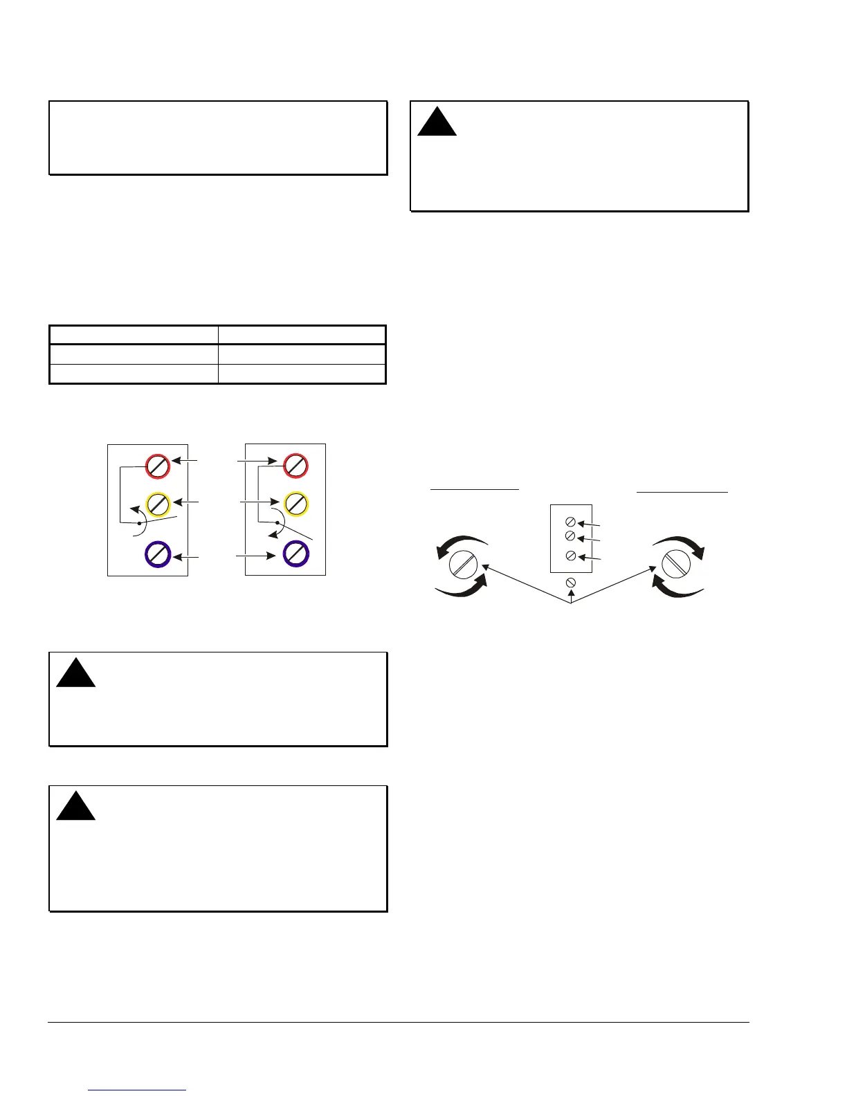
The F61KB and F61LB models have three color-coded
terminals. Red is common. See Table 2 and Figure 1
for switch action.
The F61MB and F61MG models have four color-coded
wire leads. Red is common, green is ground. See
Table 2.
Table 2: Switch Action
Flow Action Switch Closure
Increase
Red to Yellow
Decrease
Red to Blue
Red
Yell ow
Blue
Decrease in Flow
Above Setpoint
Increase in Flow
Above Setpoint
Figure 7: Switch Action
Setup and Adjustments
!
WARNING: Risk of Electrical Shock.
Disconnect power supply before making electrical
connections. Failure to follow this precaution may
result in electrical shock or death.
!
CAUTION: Risk of Improper Operation.
The switch is factory set at approximately the
minimum flow rate (see Table 3 through Table 6).
Do not set lower than the factory setting because
that may result in the switch failing to return to a no
flow position.
!
CAUTION: Risk of Equipment Damage.
Sealed settings (screws marked with black paint) are
not intended to be changed. Adjustment attempts
may damage the control or cause loss of calibration,
voiding the warranty.
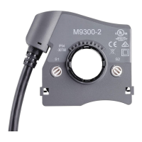
To adjust the setting of the flow switch:
1. Disconnect power supply before making electrical
connections.
2. Remove the F61 flow switch cover.
3. Turn the adjusting screw clockwise to raise the
flow rate. Turn the adjusting screw
counterclockwise to lower the flow rate. See
Figure 8.
4. Replace the cover after completing adjustments.
Tighten the cover screws to 12 in⋅lbs of torque.
Note: Do not lower the flow rate unless it has been
raised from the factory setting.
Red
Yellow
Blue
Adjusting Screw
Higher Flow Rates
More liquid flow
required to switch
from R-Y to R-B.
Lower Flow Rates
Less liquid flow
required to switch
from R-Y to R-B.
Figure 8: Flow Rate Adjustment