F61 Series Standard Flow Switches Installation Instructions 5
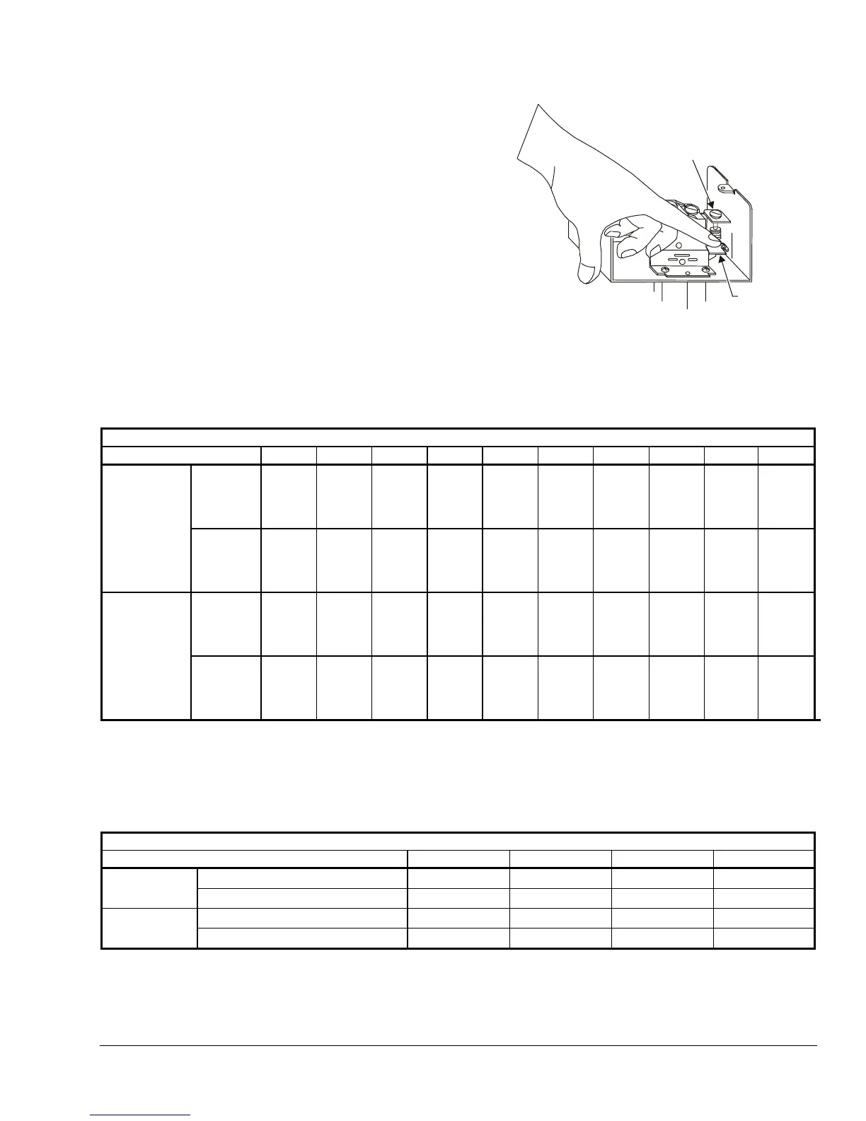
To verify that the flow rate is set above the factory
minimum (see Figure 9):
1. depress the main lever numerous times. If the
lever fails to click upon return at any time, the flow
rate is set below the factory-set minimum.
2. raise the flow rate to approximately the factory
minimum by turning the adjusting screw clockwise
until the lever clicks upon return every time.
Adjusting
Screw
Main
Lever
Figure 9: Minimum Adjustment
Typical Flow Rates for Standard F61 Flow Switches
Table 3: F61KB, F61LB, and F61MB Models, 1-3 in. Paddles
GPM (m
3
/hr) Required to Actuate Switch
Pipe Size (in.) 1 1-1/4
1
1-1/2
1
22-1/2
2
34
3
5
3
6
3
8
3
Flow
Increase
(R to Y
Closes)
4.20
(0.95)
5.80
(1.32)
7.50
(1.70)
13.7
(3.11)
18.0
(4.09)
27.5
(6.24)
65.0
(14.8)
125
(28.4)
190
(43.2)
375
(85.2)
Minimum
Adjustment
Flow
Decrease
(R to B
Closes)
2.50
(0.57)
3.70
(0.84)
5.00
(1.14)
9.50
(2.16)
12.5
(2.84)
19.0
(4.32)
50.0
(11.4)
101
(22.9)
158
(35.9)
320
(72.7)
Flow
Increase
(R to Y
Closes)
8.80
(2.0)
13.3
(3.02)
19.2
(4.36)
29.0
(6.59)
34.5
(7.84)
53.0
(12.0)
128
(29.1)
245
(55.6)
375
(85.2)
760
(173)
Maximum
Adjustment
Flow
Decrease
(R to B
Closes)
8.50
(1.93)
12.5
(2.84)
18.0
(4.09)
27.0
(6.13)
32.0
(7.27)
50.0
(11.4)
122
(27.7)
235
(53.4)
360
(81.8)
730
(166)
1. Values for 2 in. paddle trimmed to fit pipe.
2. Values for 3 in. paddle trimmed to fit pipe.
3. Values calculated for factory-installed set of 1, 2, and 3 in. paddles.
Table 4: F61KB, F61LB, and F61MB Models, 6 in. Paddles*
GPM (m
3
/hr) Required to Actuate Switch
Pipe Size (in.) 4568
Flow Increase (R to Y Closes) 37.0 (8.40) 57.0 (12.9) 74.0 (16.8) 205 (46.6)
Minimum
Adjustment
Flow Decrease (R to B Closes) 27.0 (6.13) 41.0 (9.31) 54.0 (12.3) 170 (38.6)
Flow Increase (R to Y Closes) 81.0 (18.4) 118 (26.8) 144 (32.7) 415 (94.3)
Maximum
Adjustment
Flow Decrease (R to B Closes) 76.0 (17.3) 111 (25.2) 135 (30.7) 400 (90.8)
* Where paddle size is larger than pipe size, values are for 6 in. paddle trimmed to fit pipe.