6 F61 Series Standard Flow Switches Installation Instructions
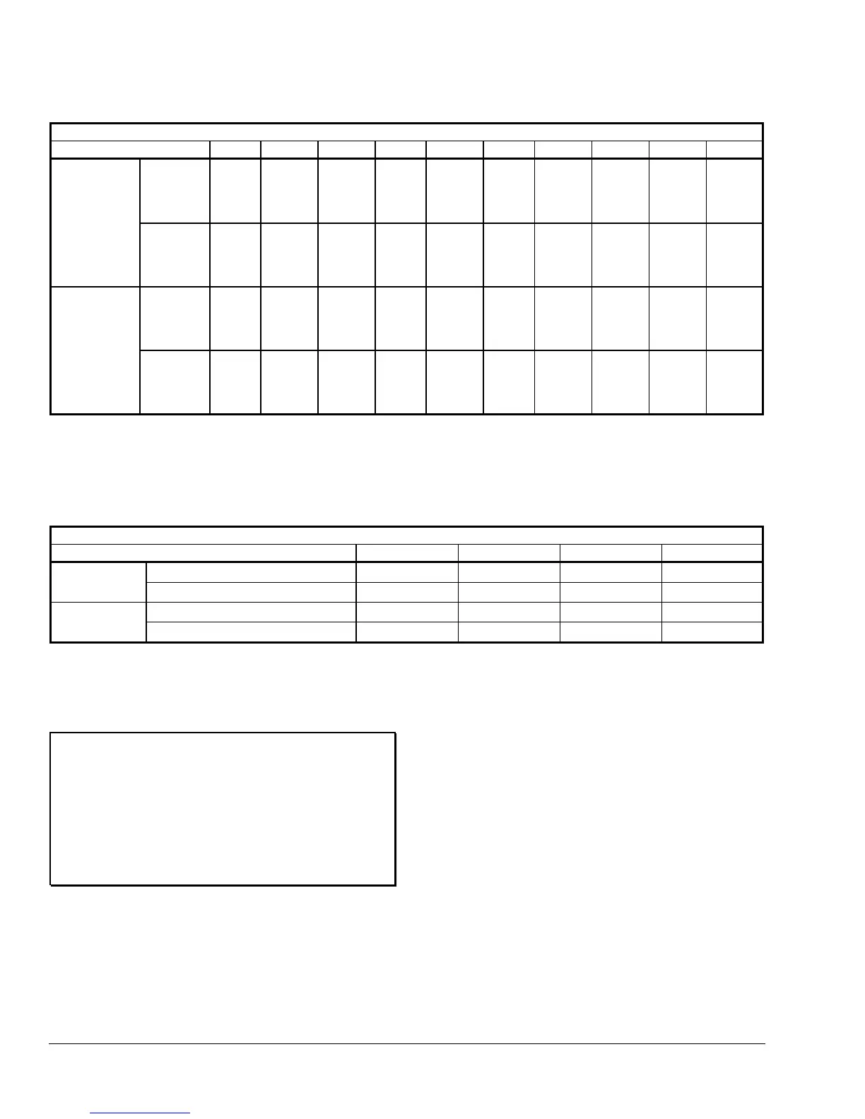
Table 5: F61MG Models, 1-3 in. Paddles
GPM (m
3
/hr) Required to Actuate Switch
Pipe Size (in.) 1 1-1/4
1
1-1/2
1
22-1/2
2
34
3
5
3
6
3
8
3
Flow
Increase
(R to Y
Closes)
3.80
(0.86)
5.30
(1.20)
6.90
(1.57)
12.7
(2.88)
16.7
(3.79)
24.3
(5.52)
61.0
(13.8)
118
(26.8)
183
(41.6)
362
(82.2)
Minimum
Adjustment
Flow
Decrease
(R to B
Closes)
2.50
(0.57)
3.70
(0.84)
5.00
(1.14)
9.50
(2.16)
12.5
(2.84)
19.0
(4.32)
50.0
(11.4)
101
(22.9)
158
(35.9)
320
(72.7)
Flow
Increase
(R to Y
Closes)
8.70
(1.98)
13.1
(2.98)
18.8
(4.27)
28.9
(6.56)
33.7
(7.65)
52.1
(11.8)
126
(28.6)
243
(55.2)
372
(84.5)
753
(171)
Maximum
Adjustment
Flow
Decrease
(R to B
Closes)
8.50
(1.93)
12.5
(2.84)
18.0
(4.09)
27.0
(6.13)
32.0
(7.27)
50.0
(11.4)
122
(27.7)
235
(53.4)
360
(81.8)
730
(166)
1. Values for 2 in. paddle trimmed to fit pipe.
2. Values for 3 in. paddle trimmed to fit pipe.
3. Values calculated for factory-installed set of 1, 2, and 3 in. paddles.
Table 6: F61MG Models, 6 in. Paddles*
GPM (m
3
/hr) Required to Actuate Switch
Pipe Size (in.) 4568
Flow Increase (R to Y Closes) 35.0 (7.95) 53.0 (12.0) 69.0 (15.7) 197 (44.7)
Minimum
Adjustment
Flow Decrease (R to B Closes) 27.0 (6.13) 41.0 (9.31) 54.0 (12.3) 170 (38.6)
Flow Increase (R to Y Closes) 80.0 (18.2) 116 (26.3) 142 (32.2) 412 (93.6)
Maximum
Adjustment
Flow Decrease (R to B Closes) 76.0 (17.3) 111 (25.2) 135 (30.7) 400 (90.8)
* Where paddle size is larger than pipe size, values are for 6 in. paddle trimmed to fit pipe.
Checkout
IMPORTANT: Ensure installation, wiring, and control
settings are according to the application
requirements. Refer to the controlled system’s
manufacturer specifications for the proper settings
when adjusting these controls.
Apply power to the control and controlled equipment.
Cycle the controlled system at least three times at
normal operating conditions.
The circuit between the red and the yellow leads
(terminals) closes when sufficient fluid flows through
the pipe to trip the F61 flow switch.