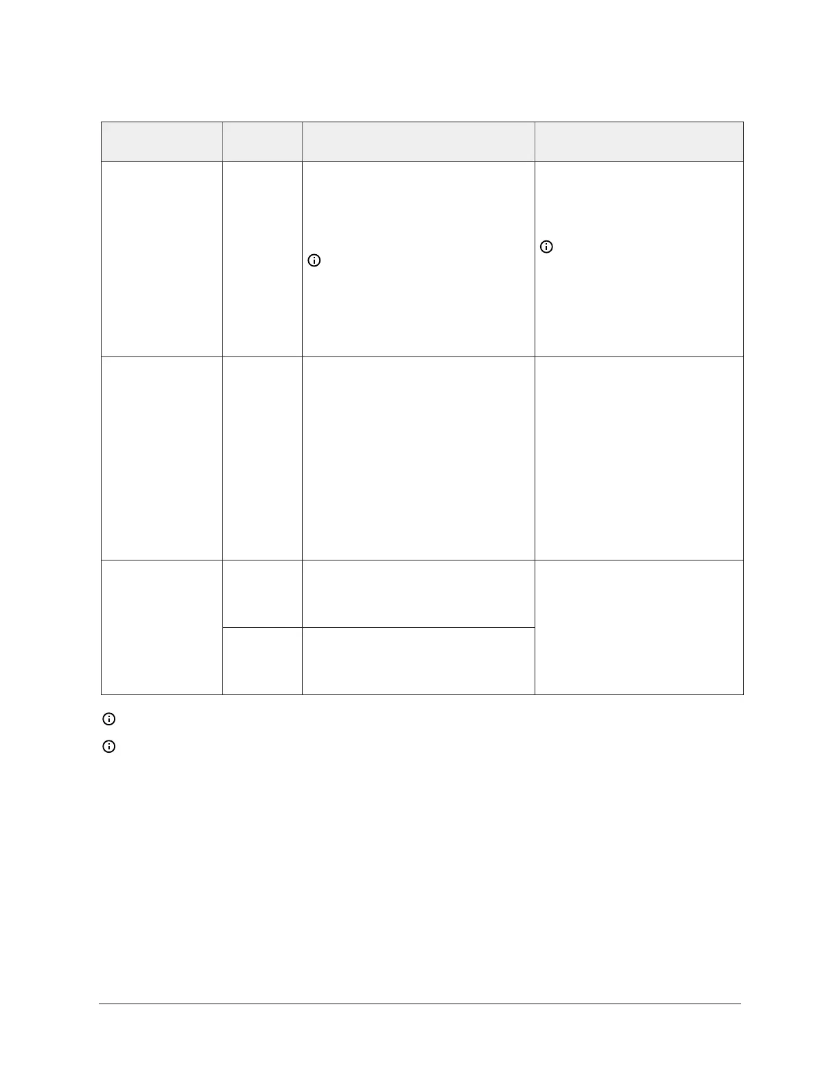
Table 5: Communications bus and supply power terminal blocks, functions, ratings,
requirements, and cables
Terminal block/
Port label
Terminal
labels
Function, electrical ratings/
Requirements
Recommended cable type
SHLD
or
SA PWR
SHLD on FC Bus: Isolated terminal
(optional shield drain connection)
SAP WR on SA Bus: 15 VDC power
lead connection.
Note: The SA PWR terminal
on an FX-PCX37 expansion
module does not supply 15
VDC. The SA bus supervisor
supplies 15 VDC to devices on
the SA bus requiring power.
SA Bus: 0.6 mm (22 AWG)
stranded, 4-wire (2 twisted-
pairs), shielded cable
recommended.
Note: On the SA Bus,
the + and - wire are one
twisted pair, and the
COM and SA PWR are the
second twisted pair of
wires.
SA/FC BUS
(Port)
RJ-12 6-Position Modular
Connector provides:
FC or SA Bus Communications
FC or SA Bus Signal Reference and
15 VDC Common
Commissioning Converter or an
FX-ZFR /ZFR Pro Wireless Router
(Maximum total current draw for
SA Bus is 100 mA.)
Bluetooth Commissioning
Converter retractable cable
or 24 AWG 3-pair CAT 3 Cable
<30.5 m (100 ft)
HOT 24 VAC Power Supply - Hot
Supplies 20–30 VAC (Nominal 24
VAC)
24~
COM 24 VAC Power Supply - Common
(Isolated from all other Common
terminals on expansion module.)
0.8 mm to 1.0 mm
(18 AWG) 2-wire
Note: See Table 4 to determine wire size and cable lengths for cables.
Note: The SA Bus and FC Bus wiring recommendations in this table are for MS/TP bus at
38,400 baud. For more information, refer to the following documents depending on your
system (FX or BCPro): FX-PC Series Controllers MS/TP Communications Bus Technical Bulletin
(LIT-12011670) or MS/TP Communications Bus for BCPro Technical Bulletin (LIT-12011908).
FX-PCX2721 Expansion Input/Output Module Installation Instructions
1
8