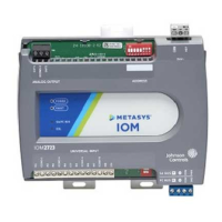
IOM3733 Input/Output Module Installation
Guide
Application
The MS-IOM3733 input/output expansion module
is part of the Metasys
®
system Field Equipment
Controller family. Input/Output expansion modules
(IOMs) expand the number of input/output points
connected to either a Network Automation Engine
(NAE), Network Control Engine (NCE), Advanced
Application Field Equipment Controller (FAC), Field
Equipment Controller (FEC), or Variable Air Volume
Modular Assembly (VMA) to monitor and control a
wide variety of HVAC equipment.
Note: The IOM3733 model is only available
in certain regions. Contact your local Johnson
Controls representative for more information.
IOM expansion modules operate on an RS-485
BACnet
®
MS/TP bus and integrate into IOMs
communicate using the BACnet MS/TP protocol
when directly connected to the FC bus.
Note: With Release 10.1 and later of the
Controller Configuration Tool (CCT), VMAs, FECs,
and FACs can be configured to communicate
by using either the BACnet MS/TP or the N2
field bus networking protocol. The operation of
the IOM is not affected by the selection of the
BACnet MS/TP or the N2 protocol in the host
controller, when the IOM is connected to the
host controller using the SA bus.
North American emissions
compliance
United States
This equipment has been tested and found to
comply with the limits for a Class A digital device
pursuant to Part 15 of the FCC Rules. These limits
are designed to provide reasonable protection
against harmful interference when this equipment
is operated in a commercial environment. This
equipment generates, uses, and can radiate radio
frequency energy and, if not installed and used in
accordance with the instruction manual, may cause
harmful interference to radio communications.
Operation of this equipment in a residential area
may cause harmful interference, in which case the
users will be required to correct the interference at
their own expense.
Canada
This Class (A) digital apparatus meets all the
requirements of the Canadian Interference-Causing
Equipment Regulations.
Cet appareil numérique de la Classe (A) respecte
toutes les exigences du Règlement sur le matériel
brouilleur du Canada.
Installation
Observe these guidelines when installing a
controller:
• Transport the controller in the original container
to minimize vibration and shock damage.
• Verify that all parts shipped with the controller.
• Do not drop the controller or subject it to physical
shock.
Parts included
• One controller with removable terminal blocks
• One installation instructions sheet
Materials and special tools needed
• Three fasteners appropriate for the mounting
surface (M4 screws or #8 screws)
• One 20 cm (8 in.) or longer piece of 35 mm DIN
rail and appropriate hardware for DIN rail mount
(only)
• Small straight-blade screwdriver for securing
wires in the terminal blocks
*24101431140D*
Part No. 24-10143-1140 Rev. D
2019-10-01
(barcode for factory use only)
MS-IOM3733