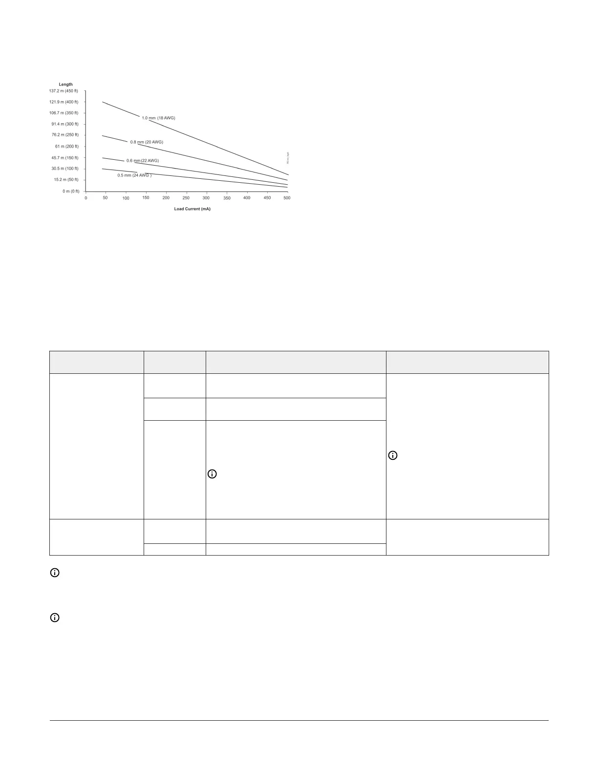
Figure 7: Maximum wire length for low-voltage
Inputs and Outputs by current and wire size
Communication bus and supply power
wiring guidelines
Communications bus and supply power terminal
blocks, ratings, and requirements provides
information about the functions, ratings, and
requirements for the communication bus and
supply power terminals; and guidelines for wire
sizes, cable types, and cable lengths when wiring
the controller's communication buses and 24 VAC
supply power.
In addition, observe these guidelines when wiring
an SA or FC bus and supply power:
• Run all low-voltage wiring and cables separate
from high-voltage wiring.
• All SA and FC bus cables, regardless of wire size,
should be twisted, insulated, stranded copper
wire.
• Shielded cable is strongly required for all SA and
FC bus cables.
• Refer to the MS/TP Communications Bus
Technical Bulletin (LIT-12011034) for detailed
information regarding wire size and cable length
requirements for the SA and FC buses.
Communications bus and supply power terminal blocks, ratings, and requirements
Table 4: Communications bus and supply power terminal blocks, functions, ratings, requirements, and
cables
Terminal block/Port
label
Terminal labels Function, electrical ratings/Requirements required cable type
+
-
FC or SA Bus Communications
COM
Signal Reference (Common) for FC or SA Bus
communications
FC BUS
or
SA BUS
SHLD
or
SA PWR
SHLD on FC Bus: Isolated terminal (optional
shield drain connection)
SA PWR on SA Bus: 15 VDC power lead
connection.
Note: The SA PWR terminal on an IOM
expansion module does not supply 15
VDC. The SA bus supervisor supplies 15
VDC to devices on the SA bus requiring
power.
FC Bus: 0.6 mm (22 AWG) stranded, 3-wire
twisted, shielded cable required.
SA Bus: 0.6 mm (22 AWG) stranded, 4-wire
(2 twisted-pairs), shielded cable required.
Note: On the SA Bus, the + and - wire
are one twisted pair, and the COM
and SA PWR are the second twisted
pair of wires.
HOT
24 VAC Power Supply - Hot
Supplies 20–30 VAC (Nominal 24 VAC)
24~
COM 24 VAC Power Supply - Common
0.8 mm to 1.0 mm
(18 AWG) 2-wire
Note: See Maximum wire length by current
and wire size to determine wire size and cable
lengths for cables.
Note: The SA Bus and FC Bus wiring
recommendations in this table are for MS/
TP bus at 38,400 baud. For more information,
refer to the MS/TP Communications Bus Technical
Bulletin (LIT-12011034).
IOM3733 Input/Output Module Installation Guide8