EasyManua.ls Logo

Johnson Controls FX-PCX2721 User Manual

Johnson Controls FX-PCX2721
27 pages
To Next Page IconTo Next Page
Page #1 background imageLoading...
Page #1 background image
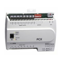
FX-PCX2721 Expansion Input/Output
Module Installation Instructions
Application
The FX-PCX2721 expansion module is part of the Facility Explorer
®
FX-PC Series Programmable
Controller family. FX-PCXs expand the number of Input/Output points connected to either an FX-
PCA, FX-PCG, or FX-PCV programmable controller or to a supervisory controller to monitor and
control a wide variety of HVAC equipment.
FX-PCXs operate on an RS-485 BACnet
®
MS/TP Bus and integrate into Johnson Controls
®
and
third-party BACnet systems. FX-PCXs communicate using the BACnet MS/TP protocol when directly
connected to the FC Bus.
Note: With Release 10.1 or later of the Controller Configuration Tool (CCT), PCAs, PCGs, or
PCVs can be configured to communicate using either the BACnet MS/TP or the N2 field bus
networking protocol. The operation of the FX-PCX is not affected by the selection of the
BACnet MS/TP or the N2 protocol in the host controller, when the PCX is connected to the host
controller using the SA bus.
North American Emissions Compliance
United States
This equipment has been tested and found to comply with the limits for a Class A digital device
pursuant to Part 15 of the FCC Rules. These limits are designed to provide reasonable protection
against harmful interference when this equipment is operated in a commercial environment.
This equipment generates, uses, and can radiate radio frequency energy and, if not installed
and used in accordance with the instruction manual, may cause harmful interference to
radio communications. Operation of this equipment in a residential area may cause harmful
interference, in which case the users will be required to correct the interference at their own
expense.
Canada
This Class (A) digital apparatus meets all the requirements of the Canadian Interference-Causing
Equipment Regulations.
Cet appareil numérique de la Classe (A) respecte toutes les exigences du Règlement sur le
matériel brouilleur du Canada.
Part No. 24-10144-173 Rev. G
2019-03-22
(barcode for factory use only)
FX-PCX2721-0
*2410144173G*

Questions and Answers:

Johnson Controls FX-PCX2721 Specifications

General IconGeneral
ModelFX-PCX2721
Product TypeProgrammable Controller
ManufacturerJohnson Controls
Input Points16
Input TypeDigital
SeriesFX
Output TypeRelay
Power Supply24V DC
Supply Voltage24 V AC/DC
Operating Voltage24 V AC/DC
Operating Temperature-20°C to 60°C

Summary

Application

North American Emissions Compliance

United States

FCC rules compliance for Class A digital devices in commercial environments.

Canada

Compliance with Canadian Interference-Causing Equipment Regulations for Class A digital apparatus.

Installation

Parts Included

Lists components shipped with the expansion module.

Materials and Special Tools Needed

Lists required fasteners, DIN rail, and tools for installation.

Mounting

DIN Rail Mount Applications

Details the preferred method for mounting on a 35 mm DIN rail.

Wall Mount Applications

Provides steps for mounting the expansion module directly on a wall.

Mounting Features and Dimensions

Refers to a figure illustrating mounting dimensions and features.

FX-PCX2721 Physical Features

Wiring

Terminal Blocks and Bus Ports

Input and Output Terminal Blocks

Describes location of input and output terminal blocks.

SA/FC Bus Terminal Block

Details the SA/FC bus terminal block and its connection.

SA/FC Bus Port

Describes the RJ-12 port for SA bus, FC bus, and converters.

Supply Power Terminal Block

Details the 24 VAC supply power terminal block.

Wireless Network Applications

Terminal Wiring Guidelines

Input and Output Wiring Guidelines

General guidelines for wiring inputs and outputs.

I/O Terminal Blocks, Ratings, and Requirements

Details functions, ratings, and requirements for I/O terminals.

Cable and Wire Length Guidelines

Maximum Cable Length Versus Load Current

Guidance on estimating max cable length based on load current and wire size.

Comm Bus and Supply Power Wiring Guidelines

Comm Bus and Supply Power Terminal Blocks, Ratings, and Requirements

Details functions, ratings for comms bus and power terminals.

Setup and Adjustments

Setting Device Address

Instructions for setting unique device addresses using DIP switches.

Removing Module Cover

Setting EOL Switch

UI Current Loop Jumpers

Current Loop Jumper IDs

Identifies current loop jumpers and their labels on the circuit board.

Commissioning

Troubleshooting

Repair Information

Guidance on what to do if the module fails.

Accessories

Technical Specifications

Points of Single Contact

Related product manuals