FX-PCX2721 physical features
The following figure displays the physical features of the FX-PCX2721, and the accompanying
table provides a description of the physical features and a reference to further information where
required.
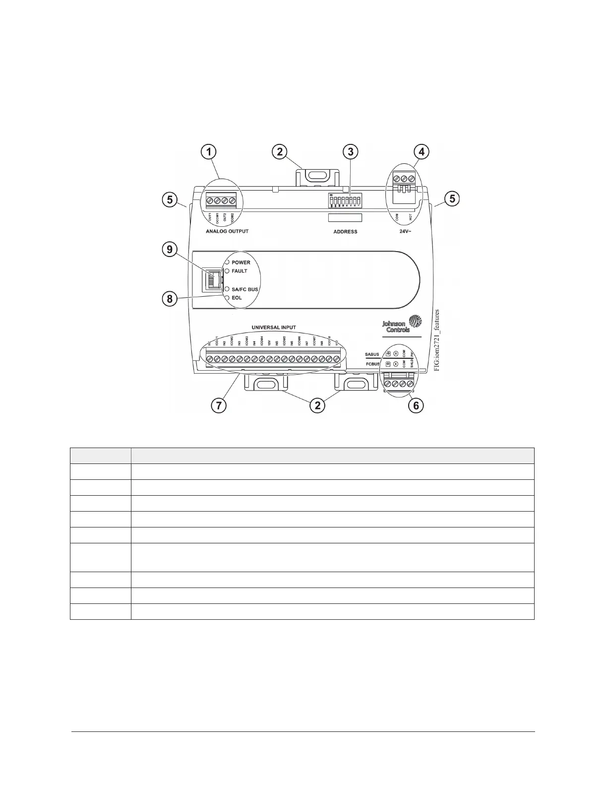
Figure 3: FX-PCX2721 physical features
Table 1: FX-PCX2721 physical features callouts and descriptions
Callout Physical feature: description and references
1 Analog Outputs (AOs) Terminal Block (see Table 3)
2 Mounting Clip
3 Device Address DIP Switch Block (see Setting the device address)
4 24 VAC, Class 2 Supply Power Terminal Block (see Supply power terminal block)
5 Cover Lift Tab (see Removing the expansion module cover)
6 Sensor Actuator (SA) Bus/Field Controller (FC) Bus Terminal Block (see SA/FC bus
terminal block)
7 End-of-Line (EOL) Termination Switch (see Setting the End-of-Line (EOL) Switch)
8 Universal Inputs (UIs) Terminal Block (see Table 3)
9 LED Status Indicators (see Table 9)
FX-PCX2721 Expansion Input/Output Module Installation Instructions6