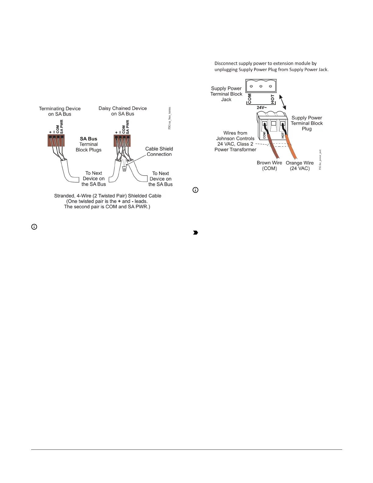
When connecting the IOM to an SA bus, wire the bus
terminal block plugs on the expansion module and
other SA bus devices in a daisy-chain configuration
using 4-wire twisted, shielded cable as shown in
Figure 5.
Figure 5: SA bus terminal block wiring
Note: The SA PWR/SHLD terminal does not
supply 15 VDC. The SA PWR/SHLD terminal
is isolated and can be used to connect (daisy
chain) the 15 VDC power leads on the SA bus
(Figure 5) or the cable shields on the FC bus
(Figure 4). The SA bus supervisor (FAC, FEC, or
VMA) supplies 15 VDC to devices on the SA bus
requiring power.
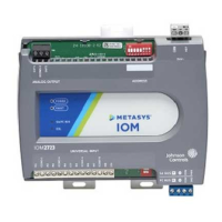
Supply Power Terminal Block
The 24 VAC supply power terminal block is a gray,
removable, 3-terminal plug that fits into a board-
mounted jack on the top right of the controller.
Wire the 24 VAC supply power wires from the
transformer to the HOT and COM terminals on the
terminal plug as shown in the following figure:
Figure 6: 24 VAC Supply Power Terminal Block
Wiring
Note: The supply power wire colors may
be different on transformers from other
manufacturers. Refer to the transformer
manufacturer’s instructions and the project
installation drawings for wiring details.
Important: Connect 24 VAC supply power to
the controller and all other network devices so
that transformer phasing is uniform across the
network devices. Powering network devices
with uniform 24 VAC supply power phasing
reduces noise, interference, and ground loop
problems. The controller does not require an
earth ground connection.
Terminal Wiring Guidelines,
Functions, Ratings, and
Requirements
Input and output wiring guidelines
The following table provides information and
guidelines about the functions, ratings, and
requirements for the controller input and
output terminals; and references guidelines for
determining proper wire sizes and cable lengths.
In addition to the wiring guidelines in the following
table, observe these guidelines when wiring
controller inputs and outputs:
• Run all low-voltage wiring and cables separate
from high-voltage wiring.
IOM3733 Input/Output Module Installation Guide 5