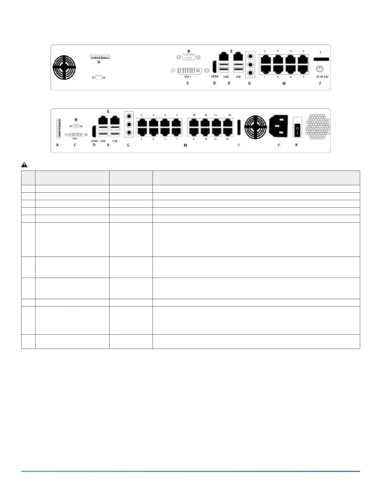
Figure 1: Back panel connectors 8 Port G-Series PoE
Figure 2: Back panel connectors 16 Port G-Series PoE
WARNING: Do not connect switches, routers, computers, printers, encoders, or non-camera devices to the PoE camera ports.
Callo
ut Component No. of ports Description
A GPIO 1 General purpose input and output currently not supported.
B RS232 or RS485 port 1 Use this port to connect to RS232 and RS485 compatible serial devices.
C DVI-I 1 Use this port to connect a digital LCD panel.
D HDMI 1 Use this port to connect to a high definition display.
E 1.0 GbE RJ45 and 2.5 GbE RJ45 2 Use the relevant port to connect to a LAN.
F USB 3.0
USB 2.0 and 3.1
4 • On the 8 port model, there are 4 USB 3.0 ports.
• On the 16 port model, there are 2 USB 3.1 ports under the 1GbE port and 2 USB 2.0
ports under the 2.5 GbE port.
Use the USB ports to connect to a USB keyboard, mouse, memory device, or DVD
burner.
G Audio connectors 3 • Blue: Line in receives audio signal input.
• Yellow: Line out, provides audio signal output.
• Red: Mic in, use to connect to an external microphone.
H PoE LAN ports 8 or 16 Depending on the model, there are 8 or 16 ports labeled cameras-only to connect the
IP PoE cameras. The LED lights on the front of the server are blue when a camera is
detected. No lights display when the camera is not detected.
I Momentary power switch 1 • On the 8 and 16 port model, press to power on the device.
J • 54 VDC input on the 8 port
model
• Power supply AC input on
the 16 port model
1 • On the 8 port model, use the input to plug in a DC power cord.
• On the 16 port model, use the input to plug in an AC power cord.
K Power supply switch 1 On the 16 port model only. Press the toggle switch to the I position to turn on the
power from the power source.
© 2023 Johnson Controls. All rights reserved. JOHNSON CONTROLS, TYCO and Exacq
are trademarks and/or registered trademarks. Unauthorized use is strictly prohibited.