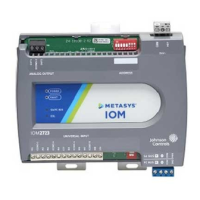
Communications bus and supply power terminal blocks, ratings, and requirements
Table 4: Communications bus and supply power terminal blocks, functions, ratings, requirements, and
cables
Terminal block/Port
label
Terminal labels Function, electrical ratings/Requirements required cable type
+
-
FC or SA Bus Communications
COM
Signal Reference (Common) for FC or SA Bus
communications
FC BUS
or
SA BUS
SHLD
or
SA PWR
SHLD on FC Bus: Isolated terminal (optional
shield drain connection)
SA PWR on SA Bus: 15 VDC power lead
connection.
Note: The SA PWR terminal on an IOM
expansion module does not supply 15
VDC. The SA bus supervisor supplies 15
VDC to devices on the SA bus requiring
power.
FC Bus: 0.6 mm (22 AWG) stranded, 3-wire
twisted, shielded cable required.
SA Bus: 0.6 mm (22 AWG) stranded, 4-wire
(2 twisted-pairs), shielded cable required.
Note: On the SA Bus, the + and - wire
are one twisted pair, and the COM
and SA PWR are the second twisted
pair of wires.
HOT
24 VAC Power Supply - Hot
Supplies 20–30 VAC (Nominal 24 VAC)
24~
COM 24 VAC Power Supply - Common
0.8 mm to 1.0 mm
(18 AWG) 2-wire
Note: The SA Bus and FC Bus wiring recommendations in this table are for MS/TP bus at 38,400 baud.
For more information, refer to the MS/TP Communications Bus Technical Bulletin (LIT-12011034).
IOM2723 Input/Output Module Installation Guide 9

 Loading...