IR Oil Mist/Smoke Detector
IR6003/7
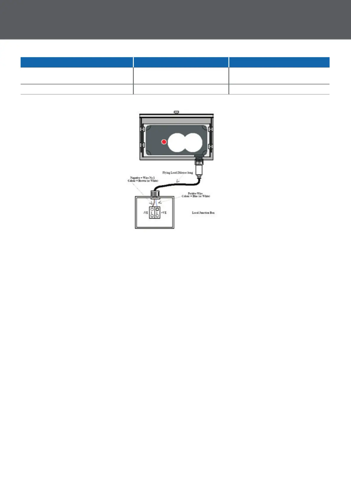
Thisdiagramshowsthedetector
connectedtoalocaljunctionboxviathe
flyinglead(01-33-14).Thelocaljunction
boxwillrequireconnectingtoourP-UIM
viaasuitablesafetybarrierwhich
providedthenecessarydetectortouser
equipmentinterface.(Fordetailssee
PowerUIM6005/2Datasheet01-33-22)
Fordetailsonhowtomountthedetector
refertoheavydutymountingbracket
Datasheet(01-33-24)
Distance Reflector Size Type
2to10M 0.6x0.6M(1x6Mx0.6M) 1
10to30M 1.2x1.2M(2x1.2Mx0.6M) 2
Commissioning
Oncethedetectorhasbeeninstalled
correctlybyconnectingittothehazard
monitoringsystemviatheP-UIM,the
usershouldpowerupthedetectorloop
andperformthefollowingconfidence
checks:
1. ThedetectorLEDblipsOnbrieflyasit
receivespowerfromtheP-UIM.The
P-UIMLifeindicatorisflashing.
2.AlsoOutputOnindicatorshouldbe
Onsteady,allotherindicatorsare
extinguished.
3.Wait20secondsandcheckthatthe
statusdetailedinstep1above
remainsunchanged.
4.Blockthebeampathofthedetector
for1minuteandcheckthatthe
detectorsignalsabeamblockedstate
(LEDflashesOnfor2seconds).The
P-UIMBeamBlockedindicatorislit
steady.Nowremovetheobstruction
fromthedetectorspath.
5.Initiateashortresetandcheckthat
theP-UIMreturnstothestatus
detailedinstep1.
6.Initiatealongresetwiththebeam
pathblockedandcheckthatthe
detectorindicatesaLifeFault(LEDis
litsteady).TheP-UIMLifeindicatoris
litsteady.Nowremovethe
obstructionforthedetectorspath.
7. Initiatealongresetandcheckthatthe
P-UIMreturnstothestatusdetailedin
step1.
Operational Parameters
ThedetectorreceivesitsDCsupplyfrom
theP-UIMandprovidesstatusreportsto
theP-UIMasfollows:
• Anormal/healthydetectorinput
conditionisindicatedwhenthe
currentis>20mAand<32mA
(normally25mA).TheLEDonthefront
ofthedetectorwillbeextinguished.
• Alow alarmconditionisindicated
whenthecurrentpulsesfromnormal
to42mAwitha1secondequalmark
spaceratioforaperiodof30seconds.
• Ahigh alarmisindicatedwhenthe
whenthecurrentpulsesfromnormal
to42mAwitha0.5secondequal
markspaceratioforaperiodof2
minutes.
• Abeam blockedconditionis
indicatedwhenthecurrentswitches
fromnormalto17mAforaperiodof
2seconds
• Acleaning faultconditionisindicated
whenthecurrentswitchesfrom
normalto17mAforaperiodof4
seconds
• Alife faultconditionisindicated
whenthecurrentfallsto17mAfor>5
seconds.
PSF330JC_Time_Saver_Mount.indd 3 27/08/2019 17:23:13
 Loading...