Troubleshooting
LED status indicators
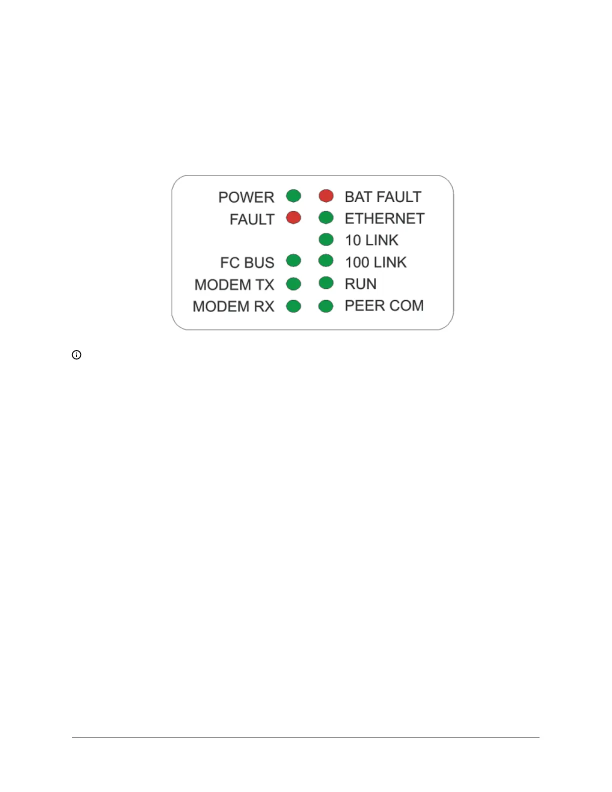
The network engine models have up to 11 LEDs (depending on the model) to indicate power
and network communication status. Figure 14 shows the LEDs and Table 8 describes the LED
indications.
Figure 14: Network engine LED designations
Note: Some of the LEDs shown in Figure 14 are not used or displayed on some network engine
models.
LED test sequence at startup
During startup, the network engine automatically initiates an LED test to verify the operational
status of the LEDs. Immediately after connecting supply power, the following LED lighting sequence
occurs:
1. The POWER, BAT FAULT, 10 LINK, FAULT, RUN, and PEER COM LEDs turn On, indicating that
the OS is booting up. (After 2 seconds, the LEDs may change states depending on site-specific
network activity.)
2. The BAT FAULT, PEER COM, and FAULT LEDs shut Off. The RUN LED flashes to indicate that the
network engine software is loading.
3. The LEDs display the status of the network engine. When the RUN LED goes On Steady, startup
is complete, and the network engine is operational.
The total time to start the network engine depends on the size of the database and can take several
minutes.
See Table 8 for more information on the network engine LEDs. Refer to the NAE Commissioning
Guide (LIT-1201519) for additional information on troubleshooting a network engine.
NAE35/NAE45 Installation Guide20