Materials and special tools needed
• three M4 (#8) fasteners appropriate for the mounting surface
• one 20 cm (8 in.) or longer piece of DIN rail and appropriate hardware for mounting the DIN rail
Dimensions
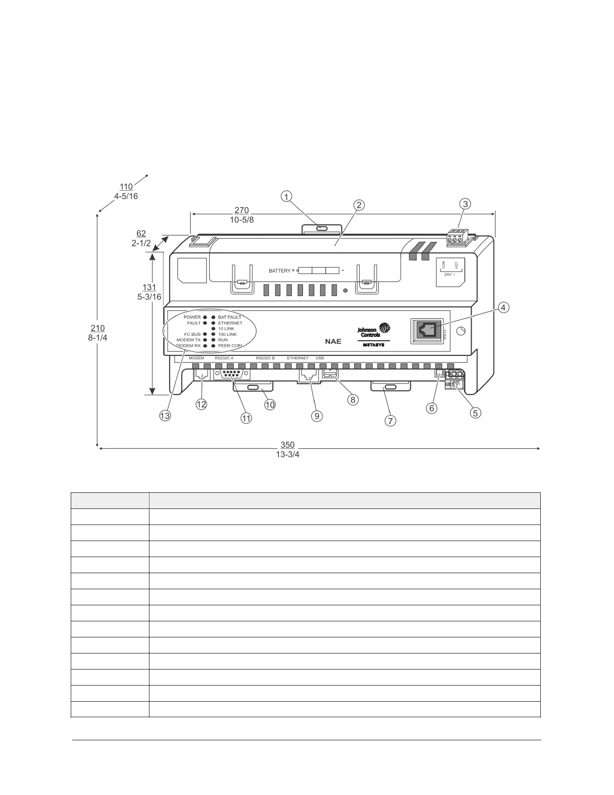
Figure 1: Front of NAE4511-2 showing dimensions (mm/in.),
physical features, and required mounting space around engine
Table 1: NAE45 physical features
Callout Description
1 Mounting clip
2 Data protection battery compartment
3 24 VAC power terminal
4 6-pin modular field controller service port
5 FC Bus (N2 Bus or FC Bus terminal)
6 End-of-line switch
7 Mounting clip
8 USB port
9 RJ-45 8-pin Ethernet port
10 Mounting clip
11 RS-232 serial port
12 Modem terminal (functional at Release 9.0; not functional at Release 9.0.7)
13 System status LEDs
NAE35/NAE45 Installation Guide2