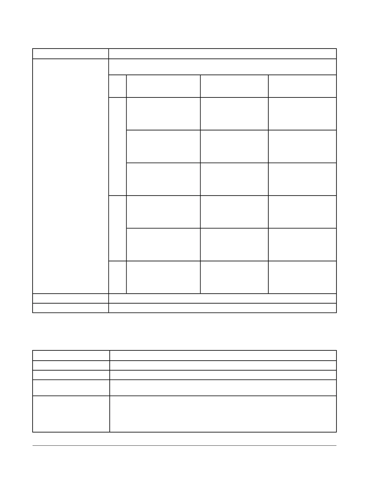
Table 5: Rules for M-Bus Protocol
Rules/Maximums AllowedCategory
Length depends on cable resistance, capacitance, number of devices, position of devices, and
configured communication speed. Example scenarios to help with calculation:
Line Length and Type
Maximum Distance for
Entire Bus
Maximum Distance
Between Converter and
Devices
Maximum Number of Unit
Loads
1, 2
Baud
Rate
5,000 m (16,404 ft)
(2 x 1.0 mm [18 AWG],
shield recommended,
resistance < 90 Ohms)
3,000 m (9,842 ft)642400
4,000 m (13,123 ft)
(2 x 1.0 mm [18 AWG],
shielded, resistance < 90
Ohms)
1,000 m (3,281 ft)64
4,000 m (13,123 ft)
(2 x 0.8 mm [20 AWG],
shielded, resistance < 30
Ohms)
350 m (1,148 ft)250
4,000 m (13,123 ft)
(2 x 0.8 mm [20 AWG],
shielded, resistance < 30
Ohms)
350 m (1,148 ft)649,600
1,000 m (3,281 ft)
(2 x 0.8 mm [20 AWG],
shielded, resistance < 30
Ohms)
350 m (1,148 ft)250
1,000 m (3,281 ft)
(2 x 0.8 mm [20 AWG],
shielded, resistance < 30
Ohms)
350 m (1,148 ft)6438,400
Twisted pair cable (shielding optional)Cable
No terminationTermination
1 Unit load is a defined standby current. A device is permitted a current drain of one unit load by default but may consume
more if it is shown at the device (by an integer) and in documentation.
2 Use M-Bus Repeaters to increase the length and the number of unit loads permissible.
Table 6: Rules for KNX Protocol
Rules/Maximums AllowedCategory
No restrictions in topologyGeneral
Depends on chosen topology and cable typeNumber of Devices
Twisted pair cable recommended; length depends on cable resistance, capacitance, number
devices, position of devices, and communication speed.
Line Length and Type
Copper, solid and stranded wires with outer sheath, one- or two-twisted pair; 0.8 to 1.0 mm (20
to 18 AWG)
Screen is required and must cover the entire diameter.
Drain wire: Diameter minimum 0.4 mm (26 AWG)
Cable
17NIE29 Installation Instructions
 Loading...


