TEC3000 Series On/Off or Floating Fan Coil and Individual Zone Thermostat Controllers with Dehumidification
Capability Installation Instructions
10
Notes:
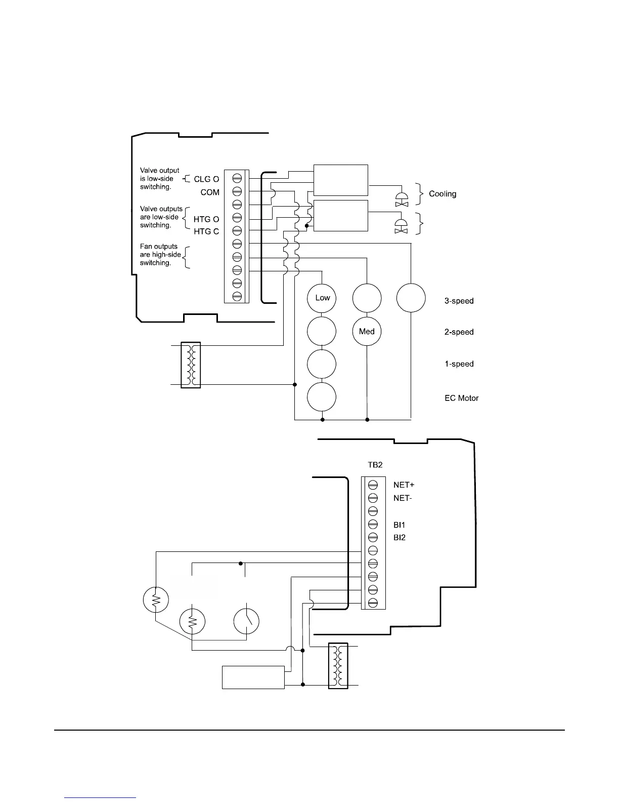
• For VAV and 2-pipe systems, connect the valve to the heating output.
• Only one transformer is required for each TEC.
Figure 7: Floating Wiring Diagram (See Table 2 for Terminal Identification)
FIG:Model 1 Wiring_floating_output
Zone Temp
Thermistor
SupplyTemp
Switch
24 V
Vin
Common
SupplyTemp
Thermistor
EC Motor
or
24 V
High
Med
FAN H
AUX
TB1
CLG C
Low
Fan
on
Fan
FAN M
FAN L
AUX
FIG:Model 1 Wiring_floating_input
Open
Hot
Close
Open
Hot
Close