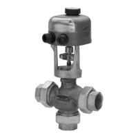
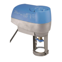
VA7820-HGx-2 / VA7830-HGx-22
Custom input signal
DIP SWITCH 3 = ON - Max range 0-10 V DC or 0-20 mA
(See Table 1 “DIP Switch setting”).
• The custom input signal limits must be applied during the
self-calibration cycle.
• FIRST, set the minimum input signal (start-point), within the range
0…6 V DC (0…12 mA) and confirm it by pressing the calibration button.
• LED illuminates a steady green for 2 sec. indicating correct entry.
If the LED illuminates a steady yellow for 2 sec., an incorrect setting is indicated and
must be re-entered.
• Set the maximum input signal, within the range 3…10 V DC
(6…20 mA) and confirm it by pressing the calibration button.
• LED illuminates a steady green for 2 sec. indicating correct entry.
• When the procedure is finished the actuator returns to its operating mode, reaching
the position corresponding to the input signal value, the LED will illuminate a steady
green.
• If the control signal changes, the actuator stem will move to the new position.
During the stem movement the LED flashes green.
Normal operating mode
• The actuator position is indicated by the end stroke cursors on the yoke.
• When the actuator moves, the green LED blinks.
• When the actuator stops, the green LED switches ON steady.
Actuator status indication
The actuator microprocessor carries out a diagnostics when a failure has been
detected. The actuator status is indicated by the LED. When the microprocessor detects
that the stem has come to an unexpected stop it initiates a retry cycle, this is repeated
three times and if unsuccessful the actuator status is switched to fault mode, the yellow
LED blinks.
If the problem is cleared during the retry cycles, the actuator continues its normal
function.
Table 2: LED indications
* If the sticking cause is removed, the actuator leaves the temporary fault mode pushing
the calibration button for at least 5 s.
**The LED switches back to green when the temperature is back to the an allowed
temperature value.
Table 3: Feedback output
Figure 7: Auxiliary Switches setting
(a). CAM for auxiliary switches.
The auxiliary switches can be adjusted by means of the two cams.
Safety Warnings
• Do not repair or replace a damaged cable, contact the nearest Johnson Controls®
commercial system wholesaler.
• Do not open the actuator other then aux switches or feedback setting.
Check out procedure
Before leaving the installation observe at least three complete operating cycles to be
sure that all components are functioning correctly. If not, please contact your supplier.
Ordering Code
Technical Specifications
IMPORTANT: If the LED illuminates a steady yellow for 2 sec., an incorrect setting is
indicated and the whole procedure must be restarted.
LED color
Status Green Yellow Red
On Power on - motor still
• Custom calibration
value out of range
• Self
-calibration rejected.
Valve stroke out of limit
(<0.315 >0.98 in.)
(<8, >25 mm).
Motor still.
Generic fault
Blink Motor running
• Temporary fault,
possible valve sticking*
• Self
-calibration rejected.
Valve stroke out of limits
(<0.315 >0.98 in.)
(<8, >25 mm).
Motor running.
High temperature**
Fast blink Calibrating Input signal failure
Off Power off
Input signal Feedback output
0...10 V or 0...20 mA 0...10 V
2...10 V or 4...20 mA 2...10 V
WARNING: Take care that auxiliary switches S1 and S2 are NOT
connected to different voltages.
(E.g. S1 120V and S2 24V NO!, S1 120V and S2 120V OK!).
CAUTION: Risk of Electric Shock.
Disconnect the power supply before making electrical connections to avoid
electric shock.
CAUTION: Risk of Electric Shock.
Disconnect supply power to the VA7820 / VA7830 Series Electric Spring
Return Valve Actuator before attempting to adjust the cover. Failure to
disconnect the supply power may result in electric shock.
IMPORTANT: Make all wiring connections in accordance with local, national, and
regional regulations. Do not exceed the electrical ratings of the VA7820 / VA7830
Series Electric Spring Return Valve Actuator.
CAUTION: Risk of Property Damage.
Do not apply power to the system before checking all wiring connections.
Short circuited or improperly connected wires may result in permanent
damage to the equipment.
Code Description
VA7820-HGA-2 Spring Return Extend, Proportional 24 V~
VA7820-HGC-2 Spring Return Extend, Proportional 24 V~, 2 auxiliary switches
VA7830-HGA-2 Spring Return Retract, Proportional 24 V~
VA7830-HGC-2 Spring Return Retract, Proportional 24 V~, 2 auxiliary switches
Product VA7820-HGx / VA7830-HGx-2
Thrust Force 225 lb (1000 N)
Power Supply 24 V~ (19…30 V~) 50/60 Hz, Class 2 Supply
Power Consumption 11 VA
Auxiliary Switch rating 230 V~ 1 A G.P. 3 A RES. 1/4 HP 6k cycles
Ambient Operating
Conditions
23 at
131°F (-5 at 55°C)
10 at 90% RH (
non-condensing)
Ambient Storage
Conditions
-40 at
176°F (-40 at 80°C)
5 at 95% RH (non
-condensing)
Feedback signal 0...10 V, with input signal 0...10 V or 0...20 mA
2...10 V, with input signal 2...10 V or 4...20 mA
Dimensions (H x W x D) 9.09 x 4.53 x 8.35 in. (231 x 115 x 212 mm)
Housing Material Self-extinguishing to UL94-V0
Protection Class IP54 (IEC 60529)
Shipping Weight 116
.4 oz. (3.3 Kg)
Compliance UL 60730 Listed Type 1 Enclosure,
File E194024 XAPX, XAPX7, CAN/CSA E60730-1
CE Mark, EMC Directive 89/336/EEC,
Low Voltage Directive 73/23/EEC
 Loading...