EasyManua.ls Logo

Johnson Controls VA7820-GG-1 Series - User Manual

Johnson Controls VA7820-GG-1 Series
21 pages
Print Icon
To Next Page IconTo Next Page
Loading...
Installation Instructions
Johnson Controls
®
is registered trademark of Johnson Controls, Inc.
All marks herein are the marks of their respective owners. © 2009 Johnson Controls, Inc.
Johnson Controls, Inc
Building Efficiency
Headquarters: Milwaukee, Wisconsin, USA
Branch Offices: Principal Cities World-wide
www.johnsoncontrols.com
VA7820-GGx-1x / VA7830-GGx-1x
Electric Valve Actuators - Spring Return Model
P/N 14-88375-25 Rev. A
Issue Date 06 2009
Figure 1: Dimensions in mm and Mounting Components
Figure 2: Mounting Positions
Figure 3: Manual Override
Question and Answer IconNeed help?

Do you have a question about the Johnson Controls VA7820-GG-1 Series and is the answer not in the manual?

Johnson Controls VA7820-GG-1 Series Specifications

General IconGeneral
BrandJohnson Controls
ModelVA7820-GG-1 Series
CategoryController
LanguageEnglish

Summary

Installation Instructions

Dimensions and Mounting Components

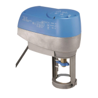
Shows physical dimensions and components of the actuator.

Mounting Positions

Illustrates correct and incorrect mounting orientations for the actuator.

Manual Override Operation

Demonstrates how to manually operate the actuator's stem.

Wiring, Calibration, and Settings

Wiring Diagram VA78 x0-GGx-xx

Provides electrical connection diagrams for various control modes.

Starting Self Calibration

Details the procedure to initiate the actuator's self-calibration process.

Auxiliary Switches Setting

Instructions for configuring the actuator's auxiliary switches.

DIP Switch Settings

Configuration options for DIP switches for signal and control type.

Product Operation and Features

General Features Overview

Overview of the actuator's general characteristics and capabilities.

Manual Positioner Functionality

Explanation of the manual positioning function and its operation.

Actuator Mounting Instructions

Step-by-step guide for mounting the actuator onto different valve models.

Input Signal Configuration

How to set up standard and custom input signals for control.

Normal Operating Mode

Description of the actuator's behavior during normal operation.

Status, Safety, and Specifications

Actuator Status Indication

Explains how the actuator uses LEDs to indicate its operational status.

General Safety Warnings

Crucial safety precautions for electrical installation and handling.

Installation Check-Out Procedure

Steps to verify correct operation after installation is complete.

Product Ordering Codes

Lists the product codes for different actuator variants.

Technical Specifications

Detailed technical data, including dimensions, power, and environmental conditions.

Related product manuals