Valve and Actuator Manual 977
Actuators and Positioners Product Information Section
Technical Bulletin VA-8052
Issue Date 0489
© 1989 Johnson Controls, Inc. 1
Part No. 14-761-0, Rev. --
Code No. LIT-977310x
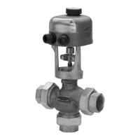
VA-8052 Electric Valve Actuator
Installation & Calibration
The VA-8052-1 motor-driven
actuator provides proportional
control of valves with up to
3/4 in. lift in heating, ventilating,
and air conditioning
applications. This non-spring
return actuator has a 50 lb force
and requires a two-wire, voltage
signal (usually 0 to 10 VDC)
from the controller, and 24 VAC
power.
Installation
!
WARNING: Equipment
Damage Hazard. Do not
drive the VA-8052 actuator
unless it is mounted to a
valve. This can result in
permanent damage to the
actuator.
Installation of VA-8052-1 on
1/4 in. and 1/2 in. Stroke Valves
1. Unpack the VA-8052
Actuator and insure that the
feedback potentiometer
plunger is on top of the
coupler arm.
2. Install the valve packing
that is provided according
to the instructions included
with it.
3. Thread the 1/4 in. Palnut,
open side down, all the way
onto the valve stem.
4. Loosely install the actuator
by sliding the actuator yoke
between the spring plate
and valve centerpiece
surface. Finger tighten the
spring plate to hold the
actuator in place (see
Fig. 1).
5. Obtain a source of 24 VAC
power and wire to the AC
and COM terminals. Wire a
source of 0 to 10 VDC to
the IN and COM terminals
(see Fig. 4). Check to see
that the stroke
potentiometer is fully CCW
(see Fig. 1).
6. Thread the knurled coupler
onto the valve stem until
approximately 1/4 in. of
thread remains between the
knurled coupler and the
Palnut. Note: It may be
necessary to pull the valve
stem up to meet the coupler
or to apply 0 to 10 VDC to
position the coupler above
the valve stem.
7. Secure the actuator in place
by tightening the spring
plate with a large
screwdriver (see Fig. 2).
8. Stroke the actuator to the
stem-up position by
applying 0 VDC. Thread
the knurled coupler onto the
valve stem until the knurled
coupler fits snugly.
9. Increase the signal slightly
(to 3 to 4 VDC) so that tension
on the coupler is relieved.
When lever stops moving,
thread the knurled coupler
on another 1 to 1-1/4 turn.
10. Reduce the signal to zero to
stroke the actuator to the
stem-up position. The limit
switch should click softly at
the full stem-up position. If
not, repeat step 9.
11. With the valve driven fully
up, thread the Palnut up the
stem until it contacts the
coupler. Tighten the Palnut
with a 7/16 in. wrench while
holding the nut on top of the
coupler with a 1/2 in.
wrench.
12. Provide an input signal of
10 VDC to the actuator.
After the actuator strokes
completely to the stem-
down position, slowly adjust
the stroke potentiometer
CW until the stem just
begins to move up. Then
adjust the stroke
potentiometer CCW until
the stem strokes down and
the limit switch clicks. Turn
the stroke adjustment an
additional 1/8 rotation CCW
to assure positive full
stroke.