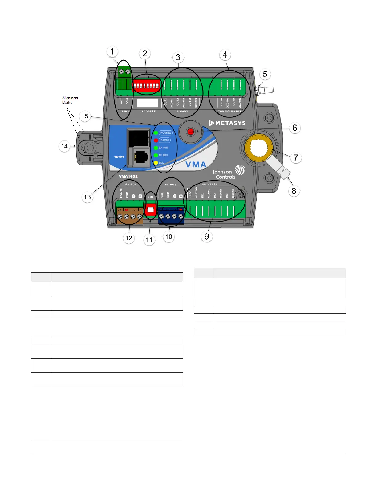
Figure 1: VMA1617/VMA1632 Controller Wiring Terminations and Physical Features
Table 1: VMA1617/VMA1632 Feature Callout
Numbers and Descriptions
Physical Features: Description and References
1
24 VAC, Class 2 Supply Power (see Supply power
terminal block)
2
Device Address DIP Switch Block (see Setting the device
address)
3 Binary Outputs, 24 VAC Triacs (see )
4
Configurable Outputs: Voltage Analog Output (0–10
VDC) and Binary Output (24 VAC Triac)
(see )
5 Dual Port Fitting
6
Manual Override Button (see Mounting for information
on using manual override Button)
7
Controller Coupler (see Mounting for information on
using the controller coupler)
8
Coupler Bolt (see Mounting for information on setting
the coupler bolt)
9
Universal Input: Voltage Analog Input (0–10 VDC)
Resistive Analog Inputs (0–600k ohm)
0–2k Potentiometer
RTD: 1k Nickel, 1k Platinum, or A99B SI
NTC: 10K Type L (10K Johnson Controls Type II is
equivalent to Type L) or 2.252K Type II
Dry Contact Binary Input
Table 1: VMA1617/VMA1632 Feature Callout
Numbers and Descriptions
Physical Features: Description and References
10
FC Bus Terminal Block. May also be used for N2
connections. Pluggable Screw (see FC bus terminal
block (Or N2 protocol as required))
11 EOL (End-of-Line) Switch (see Setting the EOL switch)
12 SA Bus Spade Terminals (see SA Bus spade lugs)
13 TSTAT Modular Port: RJ-45 8-Pin Modular Jack (see )
14 Captive Spacer and Screw
15 LED Status Indicators (see Table 10)
VMA1617 and VMA1632 VAV Controllers Installation Guide 3