ZFR1811 Wireless Field Bus Router Installation Instructions 7
Setup and Adjustments
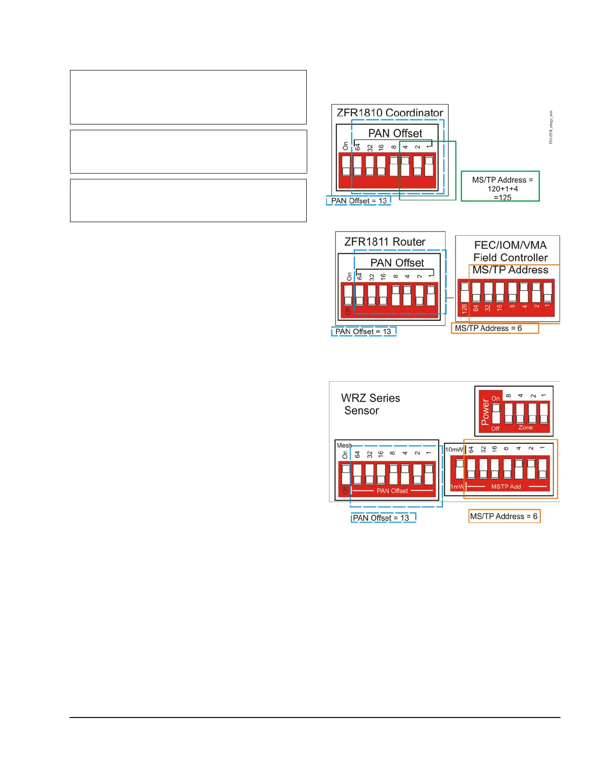
Set the PAN Offset value of the ZFR1811 Router using
the DIP switches (located on the back of the cover) to
configure the ZFR1811 Router to communicate on the
wireless mesh network. See Figure 1 and Figure 8.
The value equals the sum of the numbers set to ON.
For example, if the DIP switches labelled 1, 4, and 8
are set to ON, the PAN Offset value is 13
(1 + 4 + 8 = 13).
When selecting a PAN Offset value for a wireless
system:
• Use a unique PAN Offset value for each wireless
mesh network at a job site.
• Use the same PAN Offset value for each wireless
device in a wireless mesh network - the
ZFR1810 Coordinator and each associated
ZFR1811 Router and WRZ Sensor.
Note: On some date code labels, the switch position
numbers on the bottom of the dip switch are reversed.
In either case, the switch positions are always read
right to left.
IMPORTANT: Ensure that the PAN OFFSET
switches are set to the same value for each
ZFR1810 Coordinator, ZFR1811 Router, and
WRZ Sensor in a mesh network.
IMPORTANT: Do not connect the ZFR1811 Router
to the power supply before setting the PAN OFFSET
switches.
IMPORTANT: On the MS/TP Address switch block
of the associated FEC/IOM/VMA16 Field Controller,
set switch 128 to ON for use with a ZFR1811 Router.
Figure 8: Sample DIP Switch Settings
 Loading...