10
Original instructions
> English
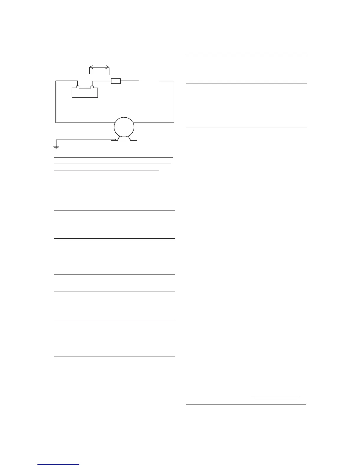
Other electrical devices, eg switch, circuit breaker,
must be installed between the pump and the posi-
tive (+) lead on the battery (on the red wire).
Wiring table
Pump
Terminal
fuse
Switch
Max 0.2
m
Red
Black
Green/yellow
+
–
Wiring dimensions
(based on 3% voltage drop)
WD 2.9
Wire size Max wire
lenght* in m
12 V 24 V
1,5 mm² # 16 AWG 5 21
2,5 mm² # 14 AWG 8 34
4,0 mm² # 12 AWG 13 55
6,0 mm² # 10 AWG 19 82
WD 3.5
Wire size Max wire
lenght* in m
12 V 24 V
2,5 mm² # 14 AWG 3 16
4,0 mm² # 12 AWG 6 25
6,0 mm² # 10 AWG 8 38
10 mm² # 6 AWG 14 63
WD 5.2
Wire size Max wire
lenght* in m
12 V 24 V
2,5 mm² # 14 AWG 3 16
4,0 mm² # 12 AWG 6 25
6,0 mm² # 10 AWG 8 38
10 mm² # 6 AWG 14 63
16 mm² # 4 AWG 22 100
* Thewirelengthisthetotaldistancefromthe
battery to the pump and back to the battery.
It is recommended to use a relay with a light wire
from main cable to switch to shorten the main
leaders.
Start-up procedure
After pump installation, the system
can be started by using the following
procedure:
• Makesuresuctionhoseisconnected
to the water supply.
• Openthespraynozzleandstart
the pump.
• Closethespraynozzlewhenwater
begins flowing and all air has been
purged from the system.
• Ifadditionalspraynozzlesortapsare
in use after the pump, open each
additional nozzle/tap until all air has
been purged from the system.
• Pumpwillcutoffaftertapsare
closed and pressure builds to the
setpoint of the pressure switch
Self-priming
Thepumpisself-primingupto2mfor
WD 2.9, 2,5m for WD 3.5 and 2,5m
forWD5.2and.Theinletpipemustbe
airtight to ensure self-priming
Dry running
Pump will not be damaged by shorter
period of dry running. It will, however,
unnecessary reduce your battery power.