..
,·
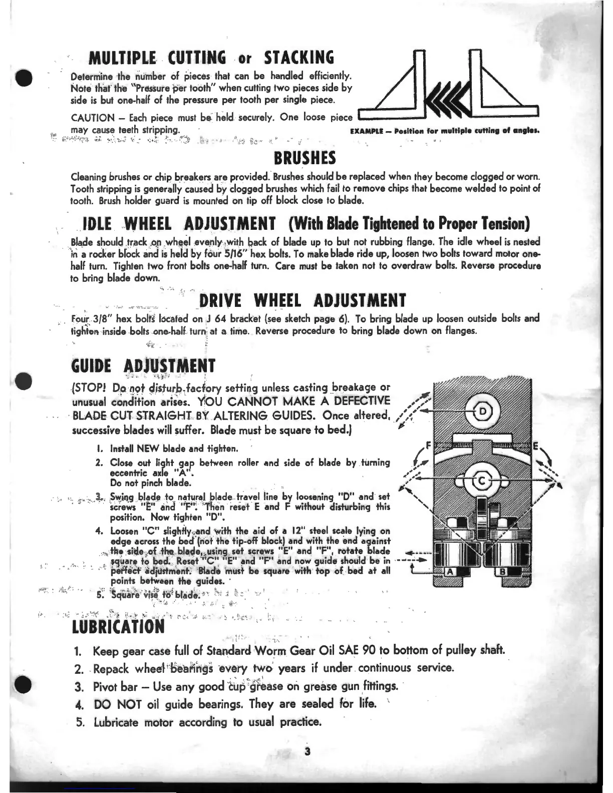
MULTIPLE
-
CUTTING
or
STACKING
Determine the number of pieces that can
be
handled efficiently.
Note that' the "Pressure
per
tooth" when cutting two pieces side
by
side
is
but one-half of the pressure
per
tooth
per
single piece.
CAUTION -
Each
piece
must
b~
~
held. securely.
One
loose piece
'------'
1
,.
may cause teeth stripping. EXAMPLE- Position
for
multiple cutting
of
anti••·
.
;~
··
.·.
~
..
~,:
.
;
~~.
:
..
.
_::_
··
..
:·
;.
-
~
·
•
.•
.
~
:
~
·
~
-
!~"":~
.J
~
...
~
.,:
~
;
...
:
Jl
••
1.'.:.·
.'>
BRUSHES
Cleaning brushes or chip breakers
are
provided. Brushes should
be
replaced when they become clogged or worn.
Tooth stripping
is
generally
cau;ed
by
clogged brushes which fail to remove chips that become
welded
to point of
tooth.
Brush
holder guard
is
mounted on tip off block close
to
blade.
IDLE
.
WHEEL
A~J~SlMENT
(With
Blade
Tightened
to
Proper
Tension)
..
.
Bla
_
de
should
.tr
.ack
.0
.
!1
.wheel
eve
.
nly
·.
~
with
b,ack
of blade up to but not rubbing flange. The idle wheel
is
nested
in
a rocker brock and
is
held
by
four 5/16"
hex
bolts.
To
make blade ride up, loosen two bolts toward motor one-
half turn. Tighten two front bolts one-half turn. Care must
be
taken not to
overdraw
bolts . . Reverse procedure
to bring blade down.
•.., • •
I,
,•,
·--
-·::
·
:-
.~-
·.;,.
-.·.
DRIVE
WHEEL
ADJUSTMENT
: .
~
..
Fou(3/8"
hex
bolt~
located on !J
64
bracket (see sketch
page
6).
To
bring blade up loosen outside bolts and
tight~n
inside bolts one.
halt
turn
'·
at a time ..
Re~erse
procedure to bring blade down on flanges.
GUIDE
ADJ
'
USTMENT
._
·_ .. ..
.....
:;.
;!;
..
-"
;,
. ,
.
(STOP!
q_o
·
~ot
qi5turp
1
fac~ory
setting
unless
casting breakage
or
unusual
condition
arises.
'(!OU
CANNOT
MAKE
A
DEFECTIVE
. , ,
·
BLADE
CUT-ST.RAIGHL
BY
.
ALTERING
GUIDES.
Once altered,
/',(
successive
blades
will
suffer.
Blade
must
be
square to
bed.)
;.
I.
Install NEW blade and tighten.
2. Close out light
gap
between roller and side of blade by turning
eeeentrie axle
"A".
Do
not pinch blade.
, ". :·
-~
·
·
·
,
S~i11
,
g
!?lade .
to
. natural
.
bl~de
..
travel line by loosening
"0"
and set
. • screws
"~"
and
"F": 'Then reset E and F without disturbing this
position. Now tighten "D".
4. Loosen
"C"
slightly
.;
and '
with
the aid of a
12"
steel seale lying on
edge
across the bec:f(not the tip-off
block)
and
with
the end against
.. ,, the .
-side
~
of
.
the,
b.la~e,
:.
using
set
ser~ws
"E" and "F", rotate blade
,
$q4ar~
to
bed
.'
.Res~t
"
'"C':
"E" and
"F"
and
now
guide should be
in
· '
petfeef
adjustment. Blade must
be
square
with
top
of bed
at
all
points between
the
guides. ·
,.
;;
.
'
'
~-
'
• .
5
~
:
~cjil~~e
vis~
;
tei
; blade,
''
I'
' : · :
0
• I
r'
'
,..:;
.
~
• +
..
.:.
',
i
1.
Keep gear case
full
of
Sta~ard
Worm
Gear
Oil
SAE
90
to bottom of pulley shaft.
2 . . Repack wheel
1
·
bearings
·eve·ry two years
if
under continuous service.
3. Pivot bar -
Use
any good
c~p
~
gt~ase
on grease gun fittings.
4.
DO
NOT
oil
guide bearings. They
are
sealed for
life.
'
5.
Lubricate motor according to usual practice.
3
 Loading...