Calibrate ohmmeter
on
appropriate scale. Con-
nect between jumpers. Meter must show:
• 9.9/15
R,
25130
- 900 ± 100 ohms.
• 9.9/15 (accessory stator, electric) - 760 ± 80
ohms.
To
test for a grounded condition, connect ohmme-
ter,
alternately, between each jumper and a clean
engine ground.
• Any needle movement indicates charge coil or
leads are grounded.
• Locate and repair ground, or replace charge
coil.
DR4619
Complete all circuits disconnected during this test.
Sensor Coil Test
STEP 1
Disconnect 5-pin
Amphenol
connector between
ignition
plate and power pack.
Set peak-reading
voltmeter to:
• 9.9/15 - "NEG" and "50," or "SEN" and "50"
on
Stevens CD-77 meter.
• 25/30 - "POS" and "50," or "SEN" and "50"
on
Stevens CD-77 meter.
Alternately, connect voltmeter between ignition
plate connector terminals "B," "C," and a clean
engine ground. Crank engine and observe meter
at each connection.
• Any reading indicates sensor coil or leads are
grounded.
• Locate and repair ground, or replace sensor
coil.
• If no reading
is
indicated, go to STEP
2.
IGNITION
IGNITION SYSTEM TESTS
DR4621
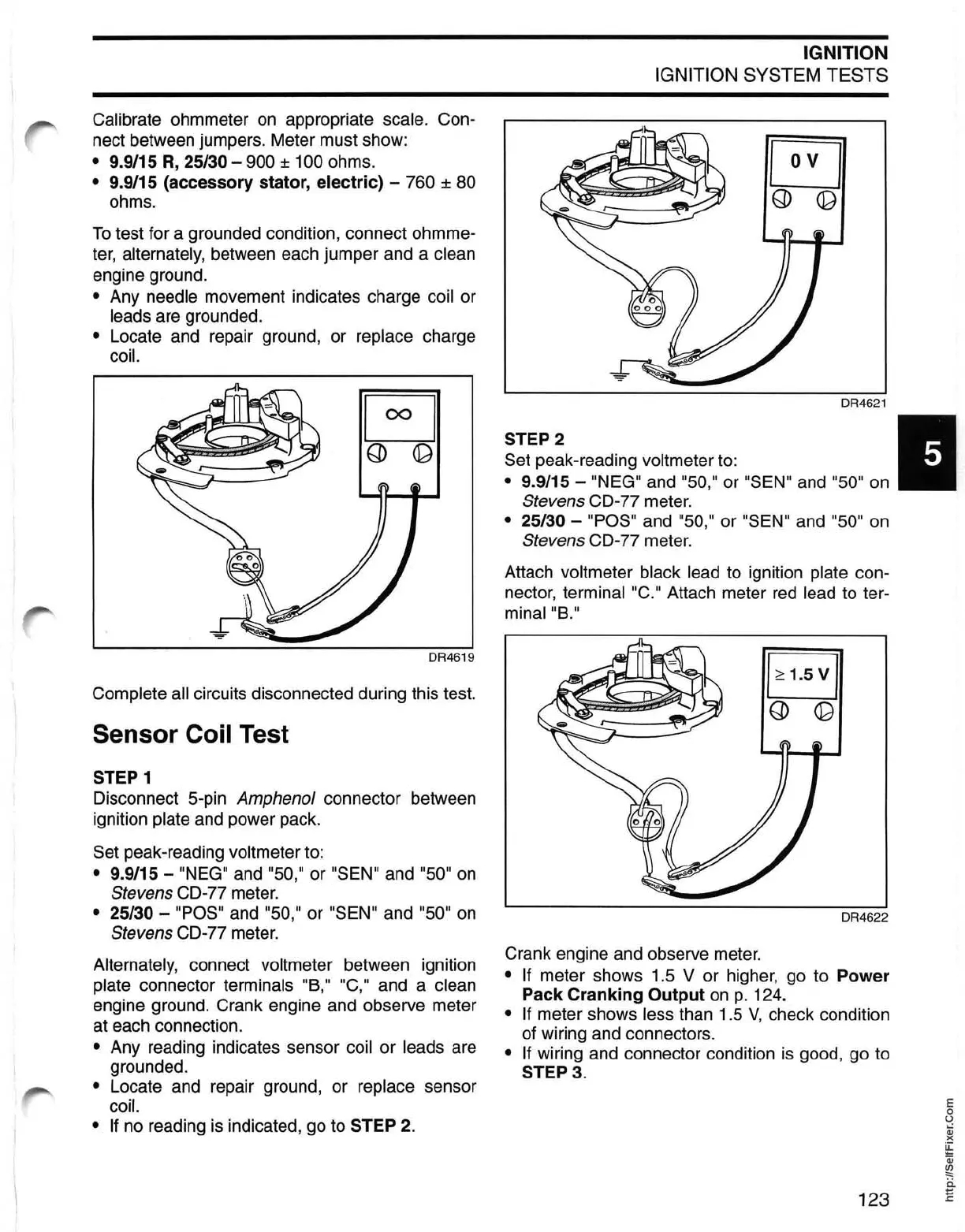
STEP 2 I
Set peak-reading voltmeter to:
• 9.9/15 - "NEG" and "50," or "SEN" and "50" on
Stevens CD-77 meter.
• 25/30 - "POS" and "50," or "SEN" and "50"
on
Stevens CD-77 meter.
Attach
voltmeter black lead to ignition plate con-
nector,
terminal "C." Attach meter
red
lead to ter-
minal "B."
DR4622
Crank engine and observe meter.
• If meter shows 1.5 V or higher, go to
Power
Pack
Cranking
Output
on
p.
124.
• If meter shows less than 1.5
V,
check condition
of wiring and connectors.
• If wiring and connector condition
is
good, go to
STEP
3.
123
E
o
U
Qj
)(
~
Qj
~
ii
E