Check for correct positioning of the float level. The
float level controls the height of fuel
in
the float
chamber and
is
essential to carburetor calibration
and function.
Turn carburetor body upside down and
hold so
gasket surface
is
horizontal. The weight of the
float will close the float valve needle. Rest Float
Gauge,
PIN
324891,
on
gasket surface and slide
gauge
up,
next to float.
Top
of float should
be
between notches
on
gauge.
Use notch that
is
indicated "9.9 & 15 HP."
Be
cer-
tain gauge
is
not holding down the float.
o
99
&I5H
.
P.
Float Gauge
I681>lf
2
THRU6H
.P.
93328
If float level
is
not between the notches of gauge,
lightly bend metal float arm to adjust level.
Be
careful not to force float needle valve into seat.
Check for correct
float drop setting. This setting
affects the
full opening of the inlet needle and
is
critical to correct operation of the carburetor.
With carburetor body
in
normal running position,
the
float must drop open from base of carburetor
body to setting shown.
Float Drop Setting - 9.9/15
1
in.
to 1 3/8
in.
(25 to 35 mm)
FUEL SYSTEM
CARBURETOR
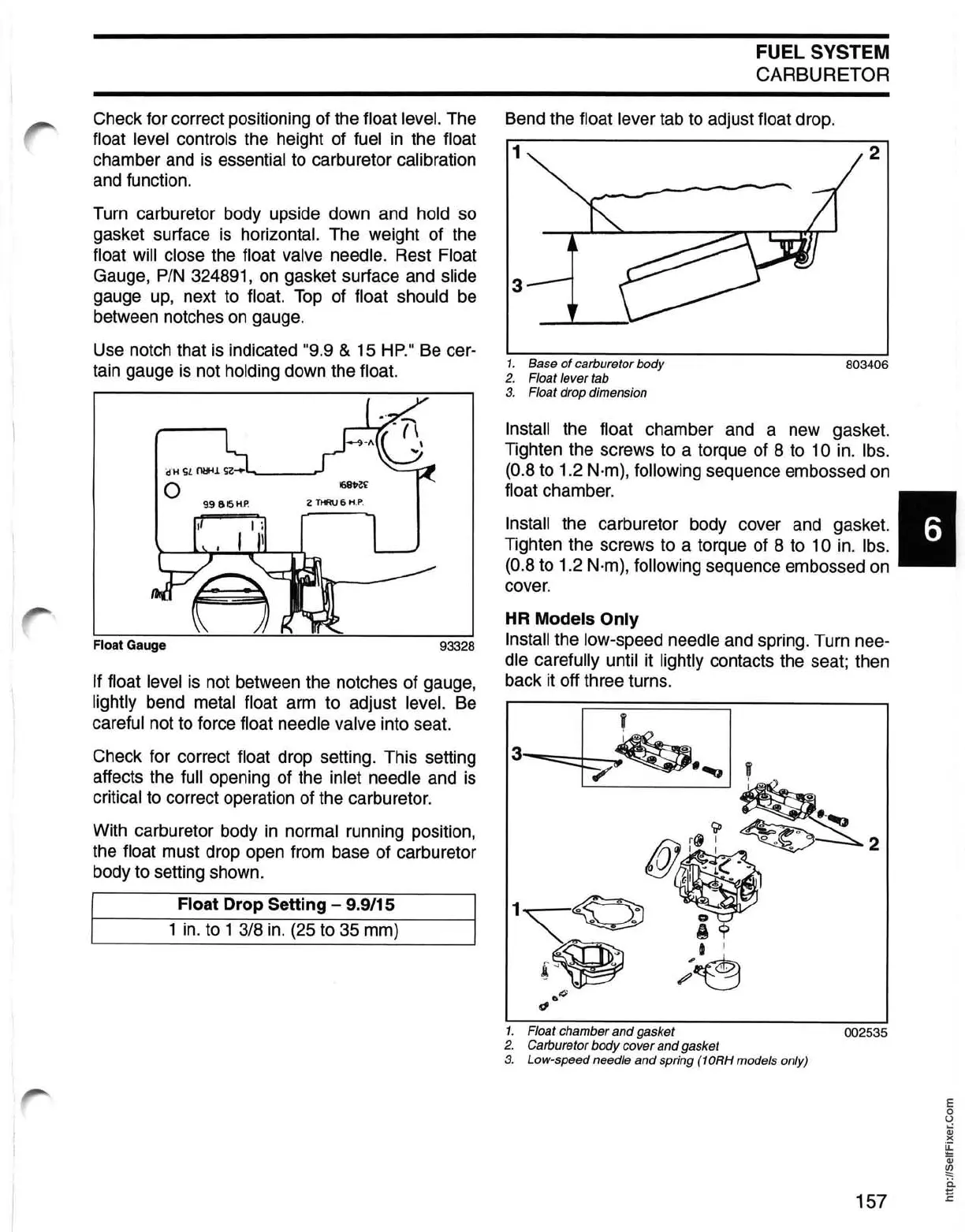
Bend the float lever tab to adjust float drop.
1
2
3
1.
Base
of
carburetor body
803406
2. Float lever tab
3.
Float drop dimension
Install the float chamber and a new gasket.
Tighten the screws to a torque
of
8 to 10 in. Ibs.
(0.8
to 1.2 N·m), following sequence embossed on
float chamber. 6
Install the carburetor body cover and gasket.
Tighten the screws to a torque of 8 to
10 in.
Ibs.
(0.8 to 1.2 N·m), following sequence embossed on
cover.
HR
Models Only
Install the low-speed needle and spring. Turn nee-
dle carefully until it lightly contacts the seat; then
back it off three turns.
1. Float chamber and gasket
002535
2. Carburetor body cover and gasket
3. Low-speed needle and spring
(10RH models only)
E
o
U
Qj
)(
~
Qj
~
ii
157 E