Remove the intake bypass cover from the cylinder
block. Clean
the gasket surfaces.
Remove
the
six intake manifold screws, intake
manifold, leaf plate assembly, and gaskets.
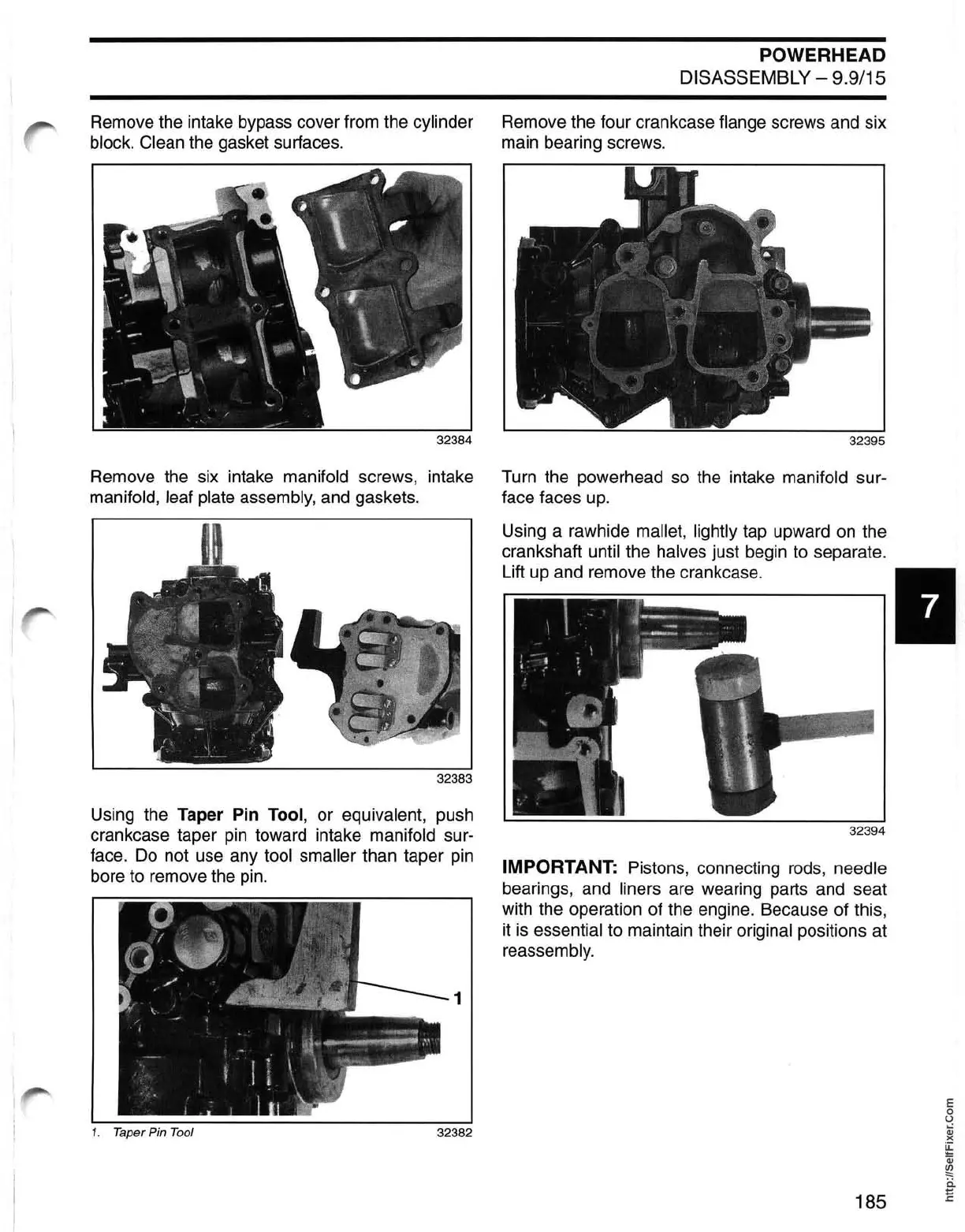
Using the
Taper
Pin
Tool, or equivalent, push
crankcase taper
pin
toward intake manifold sur-
face.
Do
not use any tool smaller than taper
pin
bore to remove the
pin.
1
1. Taper Pin
Tool
32382
POWERHEAD
DISASSEMBLY - 9.9/15
Remove the four crankcase flange screws and six
main bearing screws.
Turn the powerhead so the intake
manifold sur-
face faces up.
Using a rawhide
mallet, lightly tap upward
on
the
crankshaft until the
halves just begin to separate.
Lift up and remove the crankcase. I
32394
IMPORTANT: Pistons, connecting rods, needle
bearings, and liners are wearing parts and seat
with the operation of the engine. Because of this,
it
is
essential
to
maintain their original positions at
reassembly.
185
E
o
U
Qj
)(
~
Qj
~
ii
E