3.4
N4ake
a
f
loor
protector.
The heater
shall be
placed
on a
non.combustible
f locr
protector
of 3/B inch minimum thick of asbestr)s
mill-
board or equivalent.
The f loor
protector
shall
ev.tend at least
16 inches in
front,
and
at
ieast
B inches
to each side of
and
14
inches in back of
the heater.
See
f ig.
1.
lf
the f loor
projection
of
the chimney connector is
extending
beyond
the sides or
back
of the heater. lhe
f
ioor
protector
should be
expanded
in
that
cjirection in
its f
ull width
to cov€r
the
f loor at leasl 2
in. beyond the
projected
area.
The floor
protector
should cover
the
floor in this
direction
just
up the
wall.
The
f loor
protector
may
be
placed
on the sub or
f inish
f loorirrg,
whether the
f
iooring is
combr.rstible
or
not.
The iloor
protector
shail be reaCi!y distinguishable
f
rom
the surrounding
f loor.
Assemble
the
heater
(ltem
nc ref
ers
to
part
list)-
The heater is delivered
in..
.one
package
which
contain
s:
1.
Unit 507 B with
loose
top
lid
and
loose lurnable
grate.
2. Ash drarver
(ln
space
behind ash door).
ltem no.21.
3. Combined crank/loose
handle
for operation of
turnable
grate,
door
rnechanisms and
ash
drawer.
Item no.43.
4. lncreaser 126-151 mm
f
or 6"
f lue
pipe
adaption.
Item no. 44.
5.
Plastic
bag with
piastic
Knob for the
lower
door
handle
and wooden
knob
for
crank,
r/ith screws.
6.
These instructions. Cat. no. 125408.
7.
Cast
iron
plaque.
Note: The
unit contains
loose
parls
lvhich may fall
out and
damage other
parts
if the
unit
is
tilted. Please remove the
top
lid and
the
turn-
dulY
9ldlg.
Place the
unit
on the f loor
pi'otector
according to the
clearances
given
in f ig.
1. Be
certain that the turnable
grate
is
postioned
so that the
gear
faces
down and
that
the top lid is
properly
replaced when
the unit is in
position.
The
crank
(3)
can be
perrnanently
stored on
the
turnable
grate
shaft which
protrudes
centrally
between
the two lower
doors
at the
front
of the
heater.
The
ash drawer
is
placed
in
the space behjnd
the
ash door.
lnstall the
chimney connector.
\
Jith
the heater in
place. you
can
nc!!
determine
the
path
of the
chimney ccnnector.
The connector
shall
be used to
connect the heaier
lo the
chimney.
The
connector
shall
be
made
of
noncombustible
corrosion
resistant
material
such as steel or refrac.
tory masonry.
lf
a steel connector is
to bi used. it
should
be
24
gauge
or thicker.
black or blued
steel
pipe.
A
connector
shall be as short
and straight as
poss
ibie.
A 6"
chimney
connector
should be
used.
The
healer
is
ceirvered
with
a 5
-6
adapier
which
is
to
be
attached
to the
smoke outiet.
The
adapter is
secured
to the smoke outlet
by t\ro
6
rnm
screws urhich
are delivered
with the
heater.
A
connetor'to a rnasonry
chimne,r, shail extenC
tnrough
the rnrall
to
the inner
lace
or
liner,
but
not
beyond. and
shall
be
f rrmly
cemented to masonrv. A
thimble
must
be used to
iacilitate
removal
of
the
clrimney
connecior for
cleaning. in which
case the
thimble shall
be
perma.nently
cemenled in
place
t.,ith
the crimped
end
towards the heater to allovr
any
condensate
to
drain
into
the heater.
Secure each
joint
with
3 sheet metal
screws.
A chimney connector shall
not
pass
throuqh
any
floor
or ceiling,
nor
through a {ire
wall
or
lire
partition.
lnstall
the
factory
built
chimney in accordance
with
the
chimney
manufacture!''s instructtons.
3.7.
Before
building a
lire.
With
the
chimney
connector
properly
secured
lo
the
smoke
oullet,
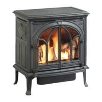
your
Jstul
coai
slove
no
507
B
is ready
tor
use. Please
read lhe
tollowing
section carefully
upon
using the heater.
4. OPERATION OF THE ROOM HEATER
NOTE:
Don't
ever
let the
unil burn with
open doors
or open
lhe venls loo
rnuch as
the combusiion then
might
be
loo intence and lhe unit
might be damaged.
Ena.
melled
heaters
must
not
be fired to !he extenl
lhat
they
assume
a
red
glow.
The enamel may lhen
be
damaged.
4.1.
This
unit can burn
various
qualities
of coal, such
as
bituminous or anthracite.
lt can aiso
burn
wood.
Please tle
certain
that the wood
has
been seasoned
f
or at least 4-6 months bef ore being burned.
4.2. When
used
with
bituminous coals:
A. Kindle
the unit with
paper
and some
smali
size
wood with
the bottom
vent
settinq at
f
ull open,
and then after
the
vrood has
been ignited, add
a
.
layer
ol coal. U/hen the
coals
have caught fire,
add
more
coal until the unit
is f illed.
When
you
are
certain that the
unit
is
burning, turn the bottom
vent
down to
2/3 turns to
'1
1/3 turns
depending
on
draf
t,
and let
the unit burn
for
at
least t hour be-
fore
adjust
jng
the settrng to the
posiijon
which
salisly
your
heai requirements. During
this
perioc!,
you
shoulC continua;ly observe the
unit
and bil
certain that
is
Coes
not
assume a recj
glow.
The
erramel wili be damaged
if
operating
under
such
cond
it ions.
8.
Bituminous
coal
vJill require
primary
air
frcm the
Veot
in the aslr door as well
as secondary
air
f
rom
the
vent
in the
feed
door at
the top of the unit.
Adjust
the secondary air
vent to
reach
a complete
combustion of ihe
gases.
4.3.
When
used
with
anthracite:
A.
Kindle with
paper
and some small
size wcod
and
then
af
ter
the
vi
ood
has
been
ignited
aCd a small
layer
of f uel. Add
more
af
ter the
f
uel bed is
ignited.
8 Anthracite requrres a
good
draft
through
the
vent
in
the bottom ash door-
ln aCCition to this.
secon-
dary
air
has
to be added
ihrough the venI
in
the
top
cjoor to reach a conrpiete combustion
of
the
Qases.
The
vents are adjusted until
you
gel
the
heat
you
need and
wrth
a clean
combustion.
C. When
using the
507
ts with
anthracite
coal, lhe use
of
a barometric damper is
permitted.
Barometric
dampers
used
in
conjunction with coal burning
units
shall comply r/ith
the
requirements
f
or draf
t
equipment.
Standard UL
328.
4
4.
V'rhen
used
wtth wood
A.
Kindie
\.vitn
paper
and
some
small size
wood and
add the amount of
wood you
need.
B.
The
draf
t is reguiated
by the vent in the
lo\4er door.
The
vent in
lhe top
feeC
door
must always be
cpeneo
slightly
f
cr aCCiticn
of second3i-y
;rir.
.F
J.Ct
 Loading...