6
1.4 Bottom Heat Shield Installation
The bottom heat shield attaches using the two 10 mm
bolts that are pre-installed in the stove bottom.
The bottom heat shield must be installed unless the stove
hearth is composed of poured concrete on earth.
1.5 Heat Shield Installation
The shields are perforated to enable you to use tin snips to
remove material to accommodate the Flue Collar position
your installation requires.
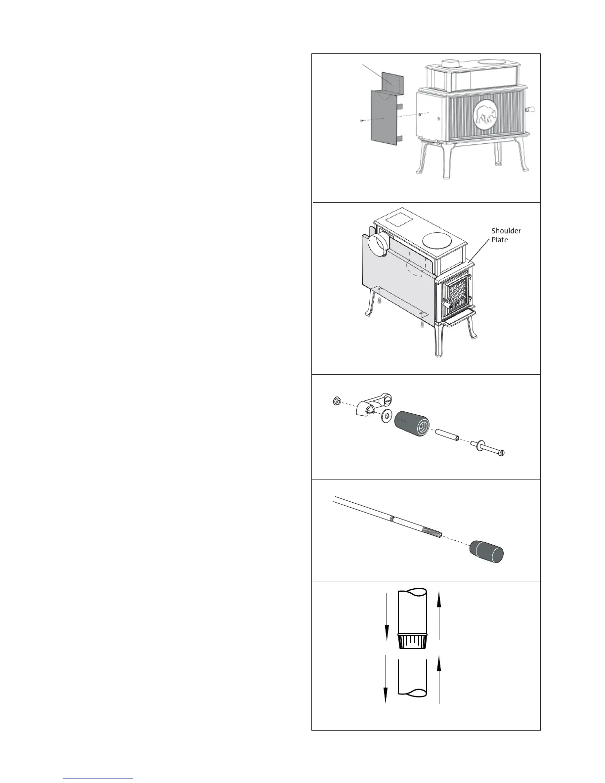
Rear Heat Shield:
1. Remove the set screw located at the center of the stove
back plate using the 3 mm hex key included with your
stove.
2. Engage the heat shield stand-offs with the slot at each
side of the back plate and attach the shield to the center
hole using the M6 x 45 hex bolt supplied. See fig. 2.
Side Heat Shield:
1. Use a 10 mm wrench to loosen the two mounting bolts
located under the lip of the stove bottom. See fig. 3.
2. Insert the stand-off clips, (attached to the backside of
the shield), under the lip of the stove Shoulder Plate and
engage the slots in the lower flange with the mounting
screws. Tighten the screws.
1.6 Assemble the Door and Control Knobs
1. Locate the white washer between the handle and the
knob and attach to the door latch as shown in fig. 4.
2. Locate the knob in the hardware bag and screw it on
to the end of the air control rod, under the ash lip, as
shown in fig.5.
1.7 Chimney Connector
Use 6” single wall or listed 6” double-wall stovepipe to
connect the stove to the chimney. Single wall stovepipe
must be black iron or stainless steel and have a minimum
thickness of 24 gauge. Do not use aluminum or galvanized
steel pipe for chimney connection - these materials are not
suitable for use with solid fuel.
Follow these guidelines regarding chimney connector
construction:
• Do not use chimney connector as a chimney.
It is intended only as a connection device.
• Each connector section must be oriented with the male
(crimped) end pointing toward the stove. See fig. 6.
• Secure all connector joints with three sheet metal
screws. The connection to the stove flue collar uses the
two M6x 16 mm self-tapping screws provided.
USA/Canada
Figure 6.
Chimney connector orientation.
Flue Gas
Direction
Tow ar d
Stove
Figure 4.
Load Door latch assembly.
Figure 5.
Install the Air Control knob.
Figure 2.
Install the Rear Heat Shield.
Cut out
section
for rear
exit flue
collar
Figure 3.
Install the Side Heat Shield.


 To Next Page