13
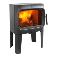
Outside air connection through rear
outlet
Fig. 5
A
1. If the external air supply is to be provided by attaching a fl ex
hose (Ø 100 mm) to the outside air connector underneath
the burn chamber, knock out the removable cover plate
(A) fi rst.
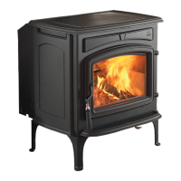
Fig. 6
100 mm
C
B
A
2. For attaching the Ø 100 mm outside air hose (A) (optional
fi tting - item no. 51012164), refer to the manual (10026187)
supplied with the outside air set. Attach the hose to the
outside air connector (B) using a hose clip (C). Terminate
the insulation approx. 100 mm below the burn chamber.
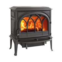
Fig. 7
A
3. Fit the supplied plate (A) to hide the outside air hose.
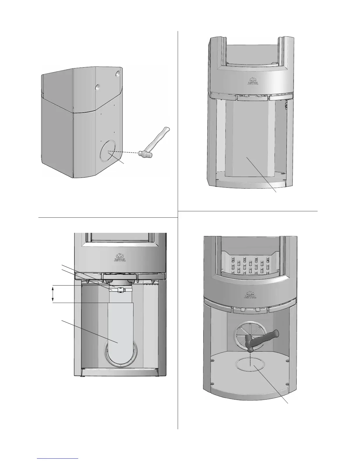
Outside air connection through the base
Fig. 8
A
4. Knock out the bottom cover (A) with a hammer.
5. Place the stove in its intended position. See fi g. 1 for
correct placement with regard to safe distances.
ENGLISH
 Loading...