15
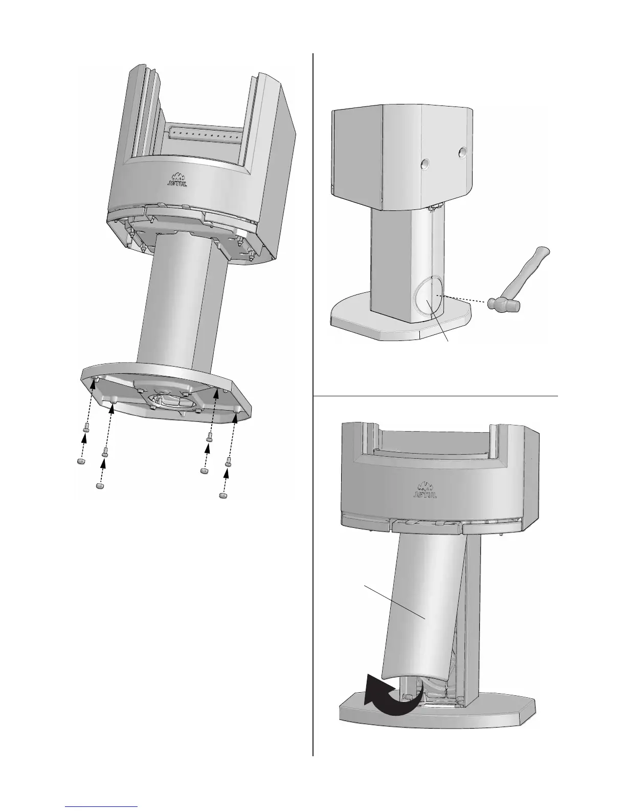
Fig. 12
A
A
A
A
1. Screw in the supplied height adjustment screws (A) with
plastic caps (B) which are in the bag of screws. NB: If
using the glass fl oor plate option, the stove must be
raised approx. 8 mm off the fl oor to allow the fl oor plate
to be slid under the front edge of the pedestal.
Outside air connection through rear outlet
in pedestal
Fig. 13
A
2. Knock out the rear cover (A) in the pedestal with a hammer.
3. Place the stove in its intended position. See fi g. 1 for
correct placement with regard to safe distances.
Fig. 14
A
1. Remove the cover (A) on the front of the pedestal by lifting it up
and forwards. Place it to one side..
ENGLISH


 To Next Page