53
Fig. 13
1.
10mm
M10x35
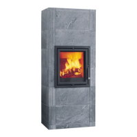
Centre the insert laterally.
2. Position the insert and the frame against the front of the
surround.
3. Make sure that there is clearance between the lower edge
of the frame and the stone below (Fig. 13 A) by adjusting the
foot screws (Fig. 13 B).
4. Adjust the foot screws until the insert is perfectly level.
Fig. 14
A
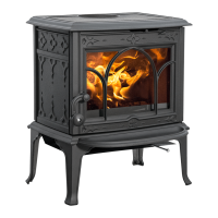
1. Use bracket 5 (Fig. 14 A) on layers no. 3 and 4.
2. Manually adjust the brackets (if necessary) to ensure the
stones are as snug as possible.
Fig. 15
A
B
223628
1. Position the angle iron so that it rests on the corner stones
223628 (Fig. 15 A).
2. The front stone (Fig. 15 B) on layer no. 5 must rest on the
angle iron.
Fig. 16
B
C
A
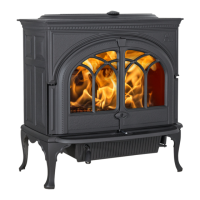
1. Install the flue pipe. Top outlet (Fig. 16 A) or rear outlet (Fig.
16 B). Remove the knockout if there is a rear outlet (Fig. 16 C).
Fig. 17
A
B
E
D
C
F
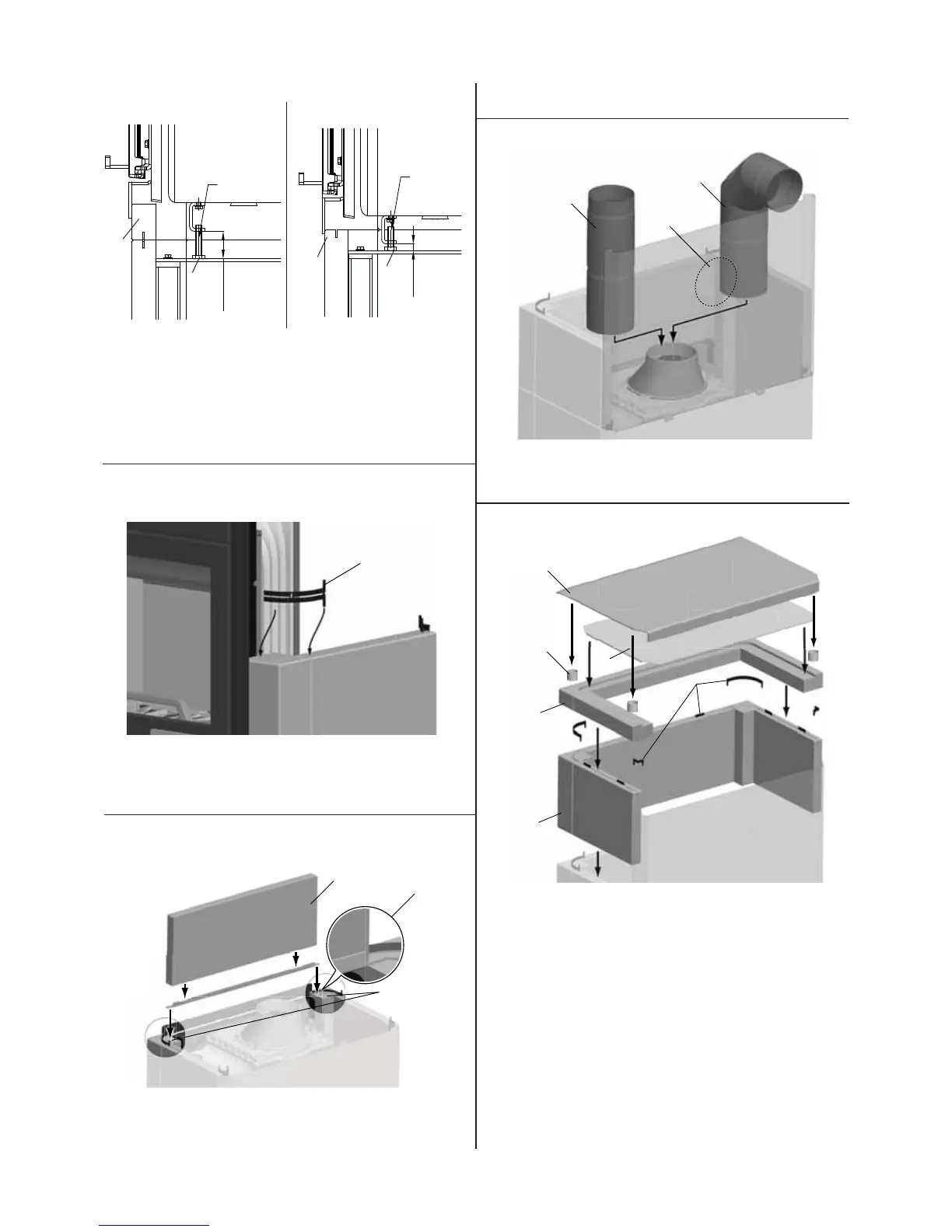
Top-mounted smoke outlet:
1. Install the last layer (Fig. 17 A) and the top layer (Fig. 17 B).
Use bracket 2, bracket 4 and bracket 6 between the last and
top layers (Fig. 17 C).
2. Remove the knockout and put the perforated top plate on
(Fig. 17 D).
3. Put the spacers in place (Fig. 17 E), remove the knockout and
put the heat shield on (Fig. 17 F).
Rear-mounted smoke outlet:
1. Install the last layer (Fig. 17 A) and the top layer (Fig. 17 B).
Use bracket 2, bracket 4 and bracket 6 between the last and
top layers (Fig. 17 C).
2. Put the perforated top plate on (Fig. 17 D).
3. Put the spacers in place (Fig. 17 E) and put the heat shield
on (Fig. 17 F).
A
B
ENGLISH
ca. 55
M10x60
A
B
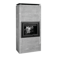
FS 165 - I 200 FL
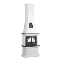
FS 165 - I 500 FL
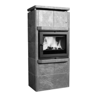
FS 165 - I 530 FL
 Loading...