C3i-M
4 - 3
4.2. IMBALANCE DETECTOR REPLACEMENT
Dismounting
- On the C3i, lift the bowl seal and remove the 3 press screws to remove the bowl. On the CR3i, remove
the front panel by unscrewing the 5 screws and disconnecting the power switch, the flat cable, the
display supply and the front panel ground cable.
- Remove the microprocessor + power pcb, disconnecting
all the electrical connections.
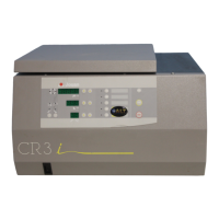
- The sensor is located on the motor stabilizer.
- Unscrew the 2 screws and remove the sensor from the
stabilizer.
Refitting
- Carry out the above operations in the reverse order.
4.3. REPLACEMENT OF THE LID LOCK ASSEMBLY
Dismounting
- Open the lid
- Remove the front panel by unscrewing the 5 screws and disconnecting the power switch, the flat cable,
the display supply and the front panel ground cable.
- Disconnect the lid lock assembly of the microprocessor + power pcb by disconnecting the J8 and J10
connectors.
- Unscrew the 4 nuts on the body of the instrument.
- Remove the lid lock assembly.
Refitting
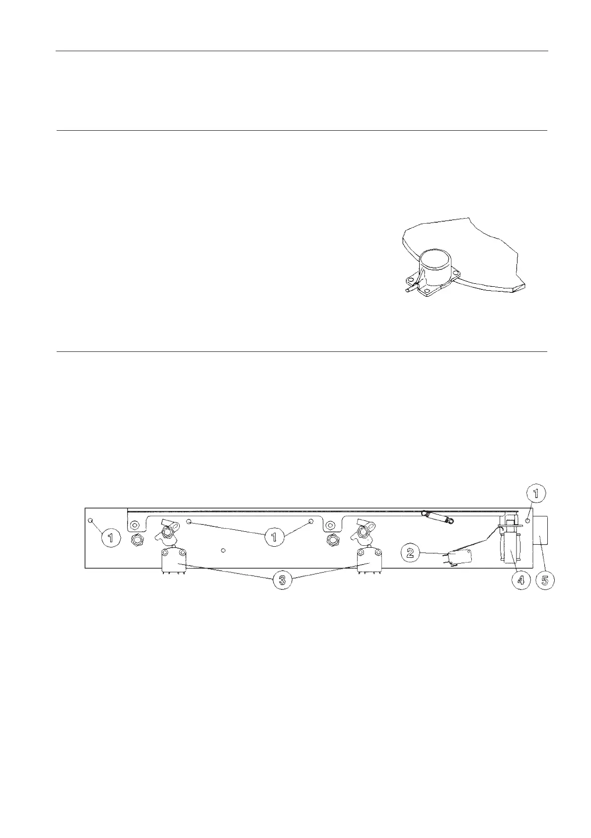
- Remount the lid lock assembly on the body, in alignment with the fixing points and keeping it in position
thanks to the nuts (1).
- Check the correct position of the lock to have a convenient lid closing.
- Screw down the nuts to the body of the instrument.
- Reconnect the electrical connectors.
- Remount the front panel.
1. Nuts
2. Solenoid microswitch
3. Lid microswitch
4. Solenoid
5. Lid handle
 Loading...