To prevent the danger from heater accidentally
loosening, the upper cover of the heater compartment is
screwed to the upper cover (Figure 4-1). Next to the
installation location it is necessary to install a strong
partition strip in front of the heater, perpendicular to the
direction of travel. Above the floor height180mm can be
attached to a septum (minimum 30*50mm).
Heat sensitive objects and flammable objects should be
placed away from the heater.
★ The exhaust cowl must be on the side wall or
ceiling.
In the exhaust cowl installed area, there is no
ventilation window in the range of 300mm, and there is
no refueling port or tank respirator in the range of
500mm.
The exhaust cowl is mounted below the window that is
close to or operable. A window switch should be installed
to ensure that the heater is turned off automatically when
the window is opened.
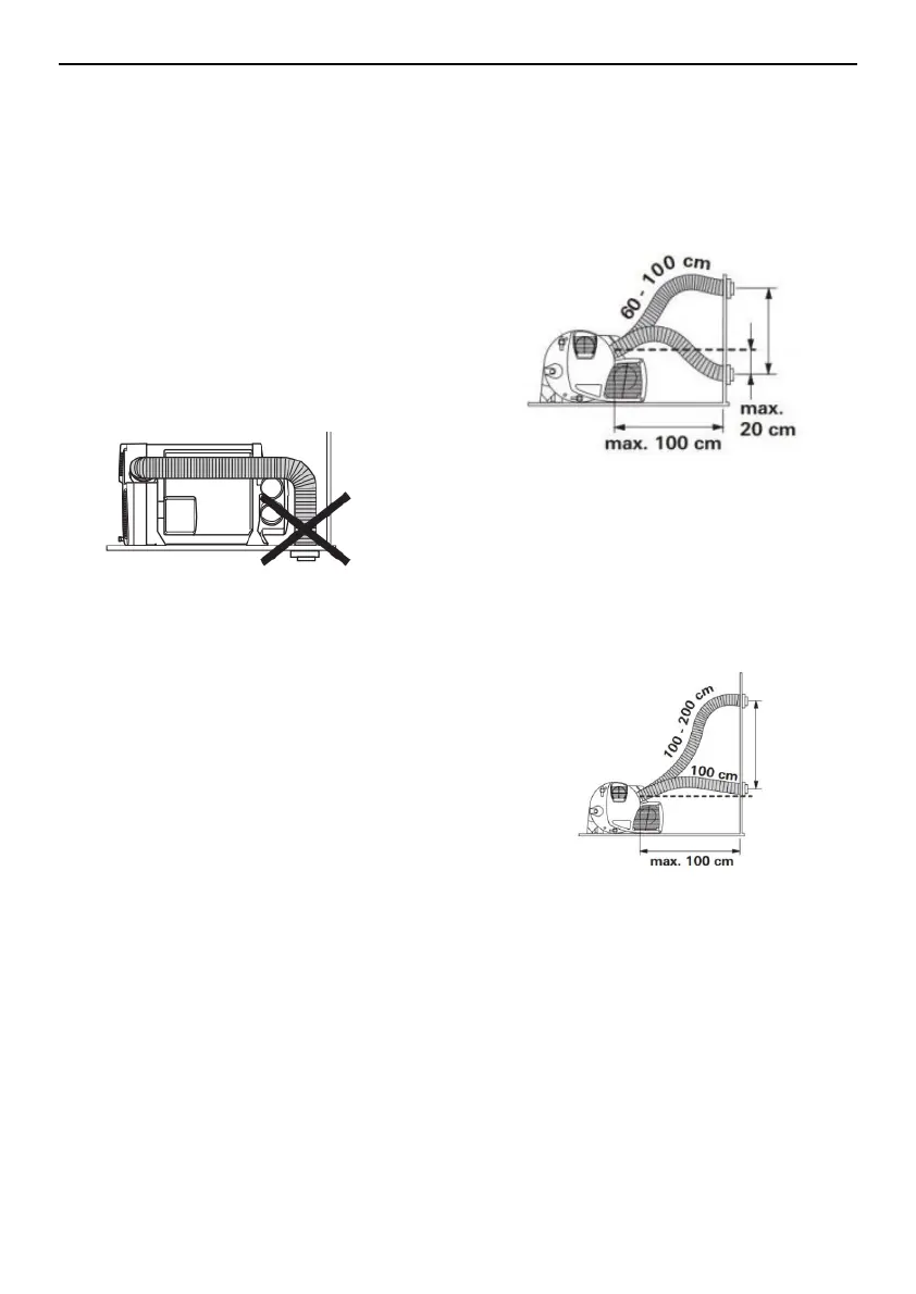
Air Inlet Hose and exhaust hose Installation
The exhaust pipe is pass through the intake pipe.
The length of the intake and exhaust pipe is as shown in
Fig. 6, and the shortest is 60cm and the longest is
100cm. The exhaust cowl is only allowed under the
exhaust outlet 20cm.
After the intake and exhaust pipes are pierced from the
through holes, they must be cut short, and the exhaust
pipes are slightly shorter than the intake pipes. Avoid
excessive expansion or tension on the exhaust pipe.
The length of the intake and exhaust pipes is 100 cm to
200 cm, as shown in Figure 7. The piping must be
arranged in the ascending direction。
The Exhaust Cowl (air inlet and outlet)
Installation
 Loading...