Warm Air Distribution
Most of the warm air is imported into the floor area of the
living compartment through the bellows.
The four air outlets on the heater are connected to the
φ65 bellows. Use only pressure piping that meets the
quality requirements of the JP. Other pipes that do not
meet our quality standards (especially wind resistance,
pipe diameter and number of ripples) shall not be used.
If the warm air duct must withstand a considerable
amount of bending immediately after the hot air outlet of
the heater in a limited space, we recommend using a 90°
elbow (Figure 3-37). This elbow can be connected to a
diameter of mm hot air duct.
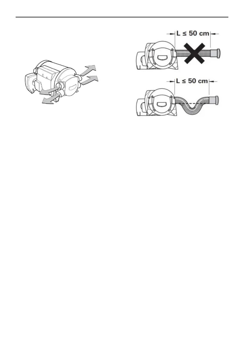
In the case where the length of the pipe is less than 2
meters, the air outlet cannot be installed at a height
higher than the connection of the warm air duct. When
the pipe length is less than 50cm, the pipe must be
siphon between the connector and the outlet. These
measures prevent the undesirable heating caused by
(fairing effect) convection of the vehicle during summer
operation.
★The warm air pipe must be firmly inserted into the
connection port.
★To get the best warm air distribution, JP recommends
using 4 warm air outlets for the heater.
★ The cross section of the heater duct must not be
reduced due to pipe connections or the analogue. That is
to say, the number of warm air duct outlets (Fig. 3_32) is
not less than four, ensuring that more than four warm air
outlets are open.
Diesel System Connection
 Loading...