If the lines are crossed, keep a sufficient distance from
the hot parts - if necessary, provide a thermal radiation
shield. The tubing installation should be able to prevent
flying stones from hitting and away from the heating
parts of the vehicle. If necessary, install protective
devices.
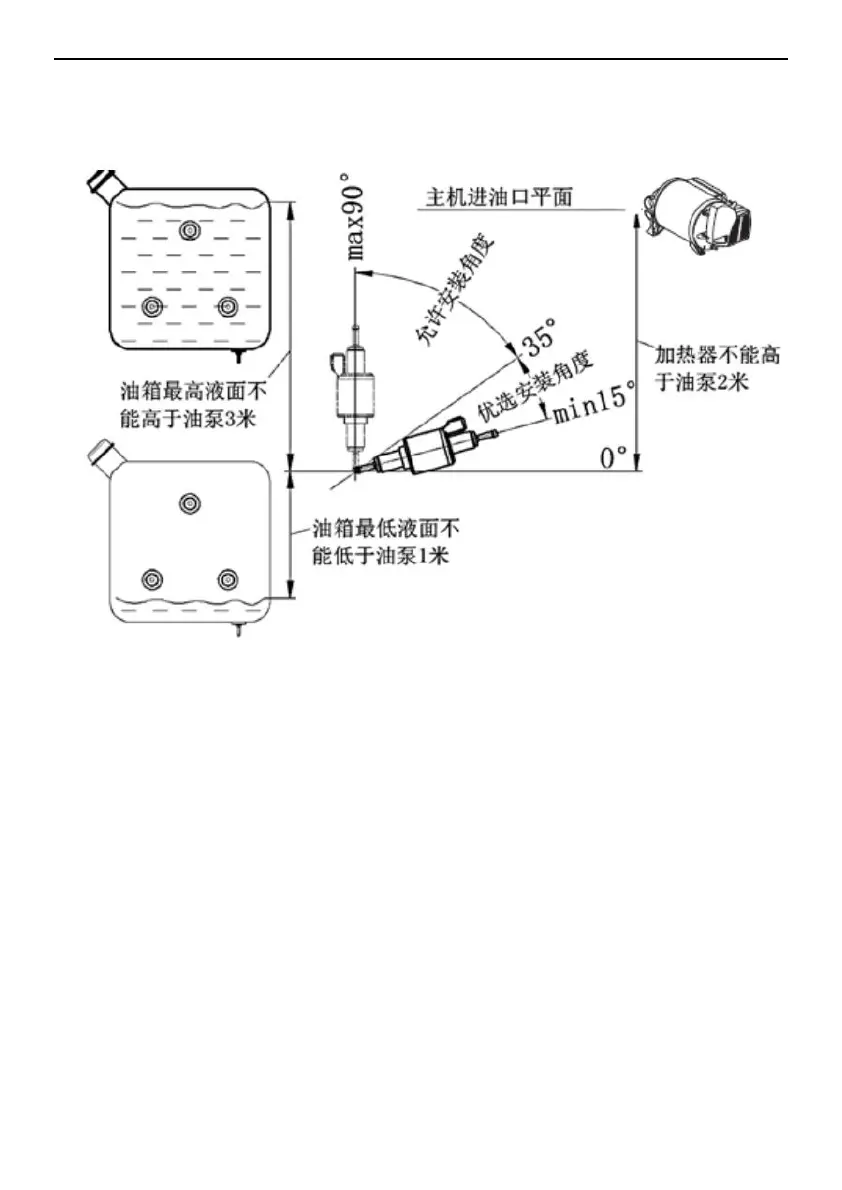
Fuel Pump Installation
The oil pump should be fixed with the oil pump fixing
ferrule (rubber). The oil pump outlet should be tilted
upwards and its installation angle should be selected
from 15° to 35° (Figure 14). When conditions permit, the
tubing from the oil pump to the heater mainframe should
gradually rise. To prevent the oil pump from being
exposed to heat (maximum operating temperature)
40 ° C), so do not install near the exhaust pipe.
The difference in height between the fuel level and the
oil pump and the height difference between the oil pump
and the main engine inlet will create pressure (or
suction) in the oil circuit, so these dimensions should
meet the requirements of Figure 14.
Heater and fuel pump connection
The direction of the tubing from the fuel pump to the
heater should be as far as possible. A hole for passing
through the fuel line and the fuel pump connection cable
is marked at a suitable location on the vehicle floor.
Before drilling, be sure to check the hidden cables, fuel
pipes, frame sections, etc.! Then use the under-body
 Loading...