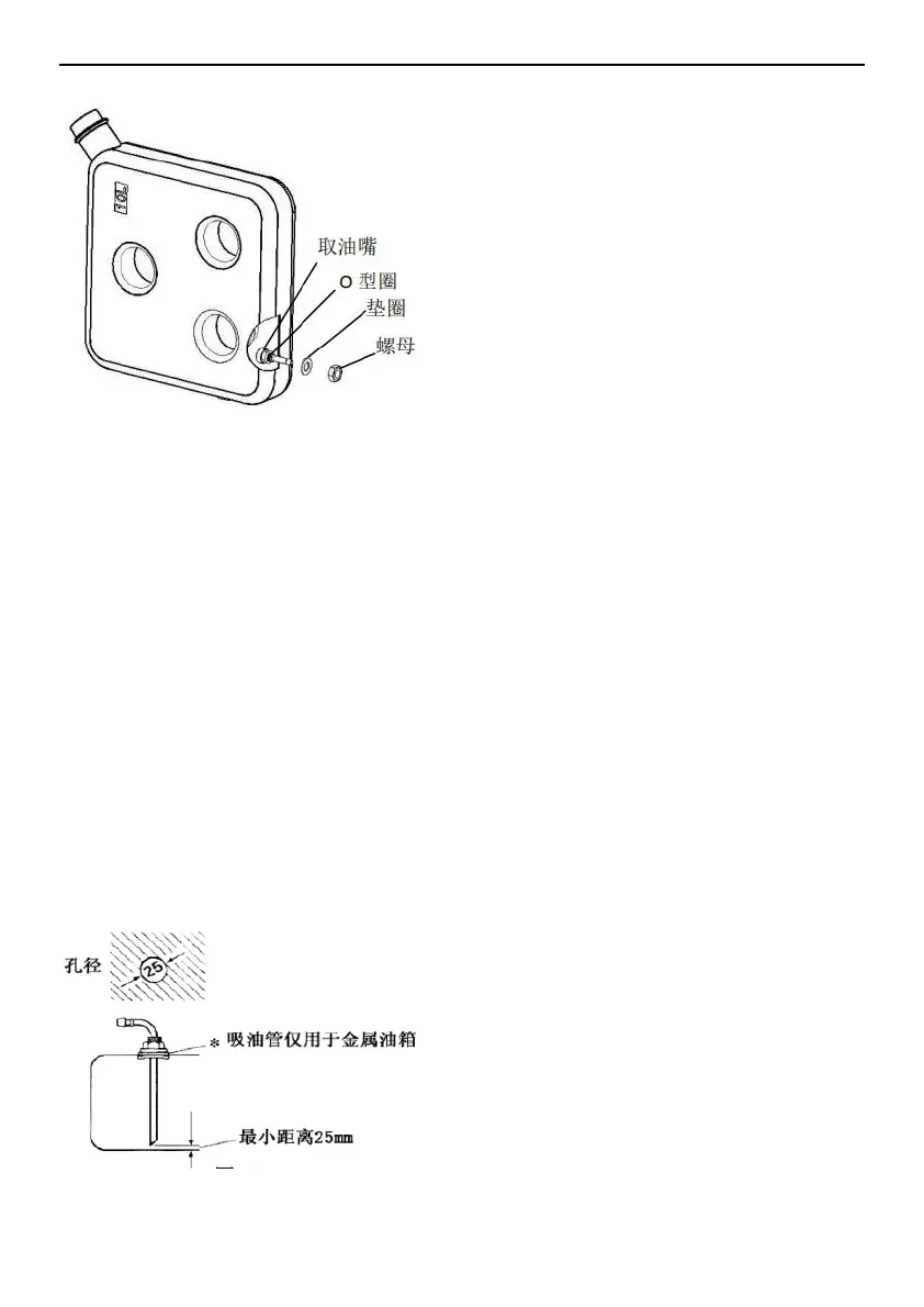
Fuel Suction pipe installation (Figure 18)
Use when drawing fuel from the vehicle's own fuel tank.
When installing, please pay attention to the installation
hole size on the fuel tank (or fuel tank cap) is φ25±0.2,
the edges are neat, and the circumference is flat to
ensure a good seal with the suction pipe socket. The
distance between the lower mouth of the suction pipe
and the bottom of the fuel tank should be 30-40mm,
which can ensure the full absorption of fuel and prevent
the inhalation of impurities deposited at the bottom of the
tank.
Water pipe connection
Water can be supplied to the tank using a pressure
pump or immersion pump with a pressure of 2.8 bar.
If the tank is connected to a centralized supply (rural or
urban connection), or if a high pressure pump is used, a
pressure reducer must be used, which will prevent
pressures above 2.8 bar.
★ The temperature rise and expansion of the water
before the relief valve is triggered may result in
pressures up to 4.5 bar (may also occur with the
immersion pump). The water pipes connected to the
water tank and the safety/drainage valve must be water
pipes that are safe for drinking water, pressure resistant
(up to 4.5 bar) and heat resistant water up to 80 °C.
Antifreeze valve (Figure 3-39, antifreeze automatic
drainer), a mechanical safety/drain valve. When there is
a danger of frost, it will automatically drain the water
from the tank through the drain.
A pressure relief valve must be installed (Figure 3-41,
0.5 MPa). If there is excessive pressure in the system,
the pressure will automatically be released intermittently
through the pressure relief valve.
External temperature sensor installation
Install the car and measure the room temperature. The
sensor installation location is determined by the RV
manufacturer based on the specific conditions of the
vehicle. When selecting the installation location, please
note that the external temperature sensor should not be
exposed to direct heat radiation.
 Loading...