22
Index
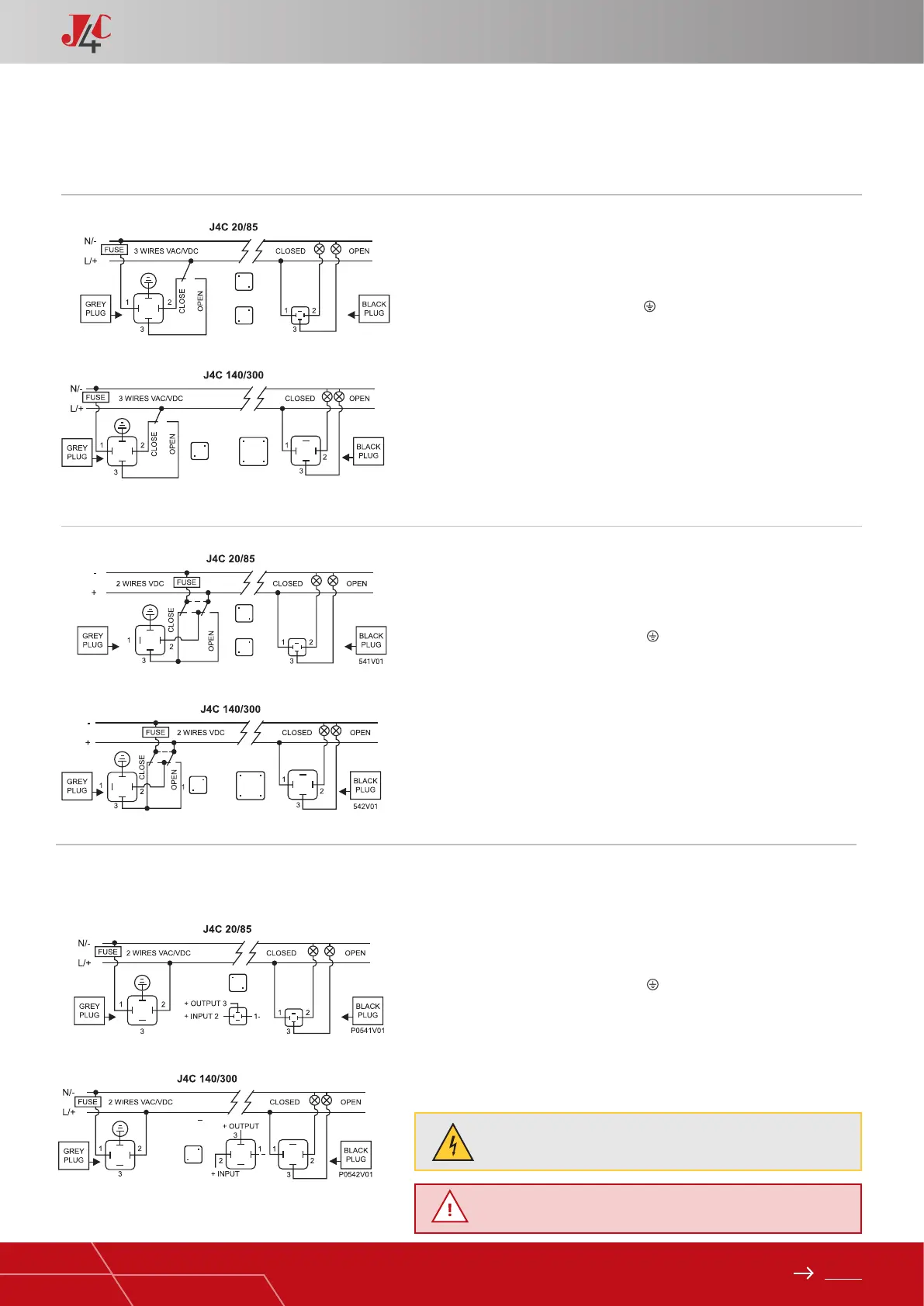
EXTERNAL CONNECTING DIAGRAM (STANDARD)
STANDARD POSITIONER EXTERNAL CONNECTING DIAGRAM
HANDBOOK / J4C SERIES
ON - OFF VAC
The power supply is connected to the grey “A” DIN plug.
Neutral PIN 1 + Phase PIN 2 = Close actuator.
Neutral PIN 1 + Phase PIN 3= Open actuator.
Earth/ground connection - Flat PIN
The volt free connection (conf. of position) black “C” DIN plug.
Common PIN 1 + PIN 2 = Close conrmation of position.
Common PIN 1 + PIN 3 = Close conrmation of position.
ON - OFF VDC
The power supply is connected to the grey “A” DIN plug.
Negative PIN 3 + Positive PIN 2= Close actuator.
Negative PIN 2 + Positive PIN 3= Open actuator.
Earth/ground connection - Flat PIN
The volt free connection (conf. of position) black “C” DIN plug.
Common PIN 1 + PIN 2 = Close conrmation of position.
Common PIN 1 + PIN 3 = Open conrmation of position.
POSITIONER VAC VDC
The power supply is connected to the grey “A” DIN plug.
Neutral/negative PIN 1 + Phase/positive PIN 2 - Power supply.
Earth/ground connection - Flat PIN
Input/output signal is connected to the black “B” DIN plug.
Negative PIN 1 + positive PIN 2 = Input signal.
Negative PIN 1 + positive PIN 3 = Output signal.
The volt free connection - black “C” DIN plug
Common PIN 1 + PIN 2 = Close conrmation of position.
Common PIN 1 + PIN 3 = Open conrmation of position.
C= Instrumentation signal no voltage
Important! Earth connector on DPS plug should not be connected
(risk of self adjustment)
A
A
A
A
C
C
C
C
A
A
B
B
C
C
 Loading...