23
Index
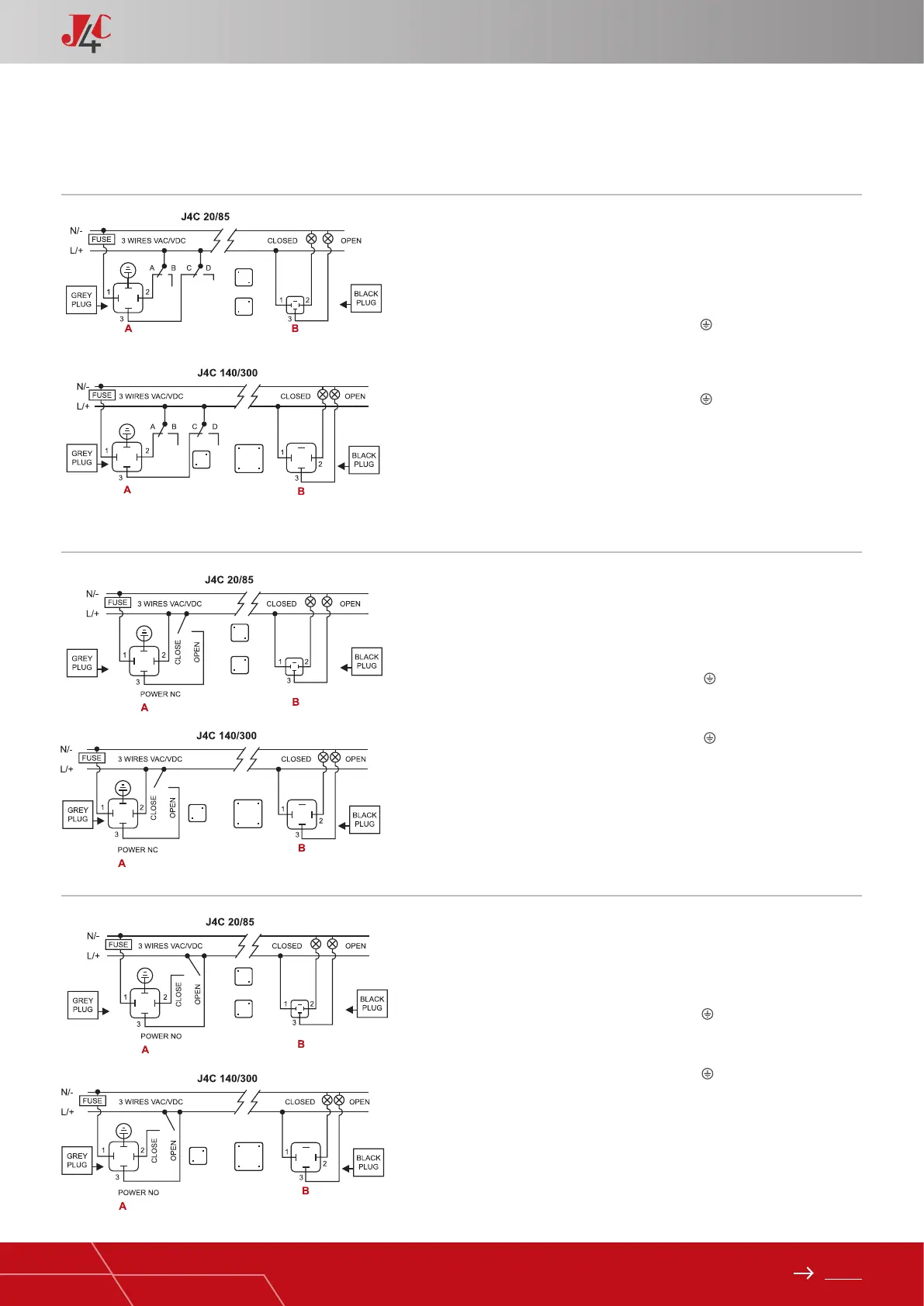
EXTERNAL CONNECTING DIAGRAM (OPTIONAL)
2 MODE ON - OFF
A = Power supply plug
A: VAC 3 WIRES (Grey plug)
PIN 1 = Neutral + PIN 2 = Phase = Close
PIN 1 = Neutral + PIN 2+3 = Phase = Open
Earth/ground connection - Flat PIN
A: VDC 3 WIRES (Grey plug)
PIN 1 = (-) Negative + PIN 2 = (+) Positive = Close
PIN 1 = (-) Negative + PIN 2+3 = (+) Positive = Open
Earth/ground connection - Flat PIN
B = Volt free contact plug
PIN 1 / PIN 2 = Close
PIN 1 / PIN 3 = Open
HANDBOOK / J4C SERIES
3 MODE ON - OFF
A = Power supply plug
A: VAC 3 WIRES (Grey plug)
PIN 1 = Neutral + PIN 2+3 = Phase = Close
PIN 1 = Neutral + PIN 3 = Phase = Open
Earth/ground connection - Flat PIN
A: VDC 3 WIRES (Grey plug)
PIN 1 = (-) Negative + PIN 2+3 = (+) Positive = Close
PIN 1 = (-) Negative + PIN 3 = (+) Positive = Open
Earth/ground connection - Flat PIN
B = Volt free contact plug
PIN 1 / PIN 2 = Closed
PIN 1 / PIN 3 = Open
Other options for external connection diagrams:
These options can be congured by the manufacturer or can be
congured by the customer, using our J4C interface kit.
STANDARD MODE · 3 WIRES ON - OFF
A = Power supply plug
A: VAC 3 WIRES (Grey plug)
PIN 1 = Neutral + PIN 2 = Phase = Close
PIN 1 = Neutral + PIN 3 = Phase = Open
PIN 1 = Neutral + PIN 2+3 = Phase = Stop
Earth/ground connection - Flat PIN
A: VDC 3 WIRES (Grey plug)
PIN 1 = (-) Negative + PIN 2 = (+) Positive = Close
PIN 1 = (-) Negative + PIN 3 = (+) Positive = Open
PIN 1 = (-) Negative + PIN 2+3 = (+) Positive = Stop
Earth/ground connection - Flat PIN
B = Volt free contact, plug
PIN 1 / PIN 2 = Close
PIN 1 / PIN 3 = Open
 Loading...