Quick Start Guide J4C S20-S300
Actuated Valves Supplies Ltd
Installation
Valve Construction
The torque required to move the valve must never exceed the rated torque of the actuator, taking into account the
medium and the pressure, and after multiplication with a sufficient safety factor.
Before mounting, any caps on the valve must be removed.
If the shaft or flange pattern of the valve cannot be mounted directly with the drive, appropriate adaptations must be
provided. The shaft must never be longer than the insertion depth of the mounting socket.
The assembly can be fixed with grub screws without additional fixings, as long as sufficient screwing depth for the
actuator is possible. In addition, care must be taken during the assembly to align the valve and actuator's operational
positions.
In this regard, it may be helpful to align the actuator by utilizing the manual override (see manual override). Depending on the fitting,
the drive angles may need to be adjusted (see cam system setting instructions).
Electrical connections
Connection of the device may only be carried out by trained and qualified personnel.
All general electrical safety regulations and VDE recommendations should apply.
The connection is made by means of the supplied industrial connectors. When wiring, pay particular attention to using the
correct cable diameter and plug seals, otherwise the IP67 rated protection cannot be guaranteed.
Each DIN plug is fastened to the actuator with a screw, care must be taken to be not be over-tightened.
J+J actuators must be connected in a monophasicly and must be controlled with either relays or switches.
Depending on your requirements, there are three different wiring methods that can be utilized.
An external fuse with appropriate rating and characteristic for motors (for example, MC switch type C) must be provided.
The unit's power must only be connected in parallel with other J+J actuators.
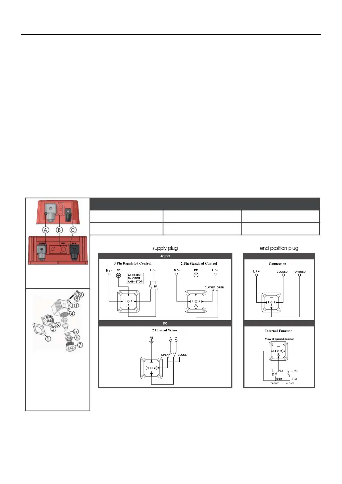
Cable Connectors
A Power Supply Plug
B Optional Plug(s)
C End of Travel Plug
1 Seal
2 Term Block
3 Clamp
4 Housing
5 Seal
6 Clamping Ring
7 Screw Fastener
8 Washer
9 Fixing Screw
10 Seal
Cable Diameter Range 8.0mm -10.5mm 5.0mm – 6.0mm
Type
DIN EN175301-803 Form A DIN EN175301-803 Form C
-PAGE 2-