76
Index
HANDBOOK / KIT DPS
9
A B
C
A
7
10
8
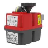
Take the DPS cover (Element A) and connect its cables, following
(Fig. A, B, C).
Mount the DPS positioner PCB (Element C), matching the cleft of
the shaft with the key inside the DPS gear.
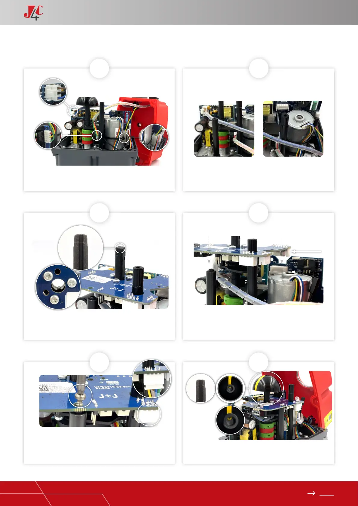
Fix the DPS positioner PCB (Element C) to the plastic column
(Element B) with the plastic xing screw (Element E) (Fig. A).
Connect the remaining cable (Element A) to the connector base
on the DPS PCB (Element C) (Fig. B).
Fix the DPS positioner PCB (Element C) to the plastic column
(Element B) with the plastic xing screw (Element E) (Fig. A).
Connect the remaining cable (Element A) to the connector base
on the DPS PCB (Element C) (Fig. B).
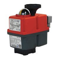
Carefully insert the position indicator, matching its inner key with
the cleft of the shaft.
Press the DPS positioner PCB (Element C) along the shaft
until the PCB connector (JP3) is plugged in the actuator PCB
connector (JP2).
Place the mentioned cables as per (Fig. A and B).
B
KIT DPS 20/85 ASSEMBLY INSTRUCTIONS — PAGE 2/3
JP3
JP2
11
A
B
12